AMAZON multi-meters discounts AMAZON oscilloscope discounts
[Note: "Tables" and various equations (denoted by "e.") are not yet avail., but coming soon.]
Circuit breakers (CBs) are an essential part of most electrical power systems, supplemented with other fault-interrupting and clearing equipment such as fuses, reclosers, and circuit switchers. The purpose of a circuit breaker is fundamentally to break a circuit. An electrical circuit is a closed path whereby current flows from a source and returns to the source. The circuit is broken when the path for the flow of current is opened and the current is reduced to a negligible or zero value. The circuit-breaking process begins with an initiating or trip signal, which may come from a protective relay or other device or from a control switch or automated control system. Some circuit breakers contain integral trip devices, whereas others require an external device to develop the trip signal. The second step is contact parting, whereby the closed contacts begin to open, spring pressure or other stored energy is released, and air, vacuum, or another insulating medium is introduced between the contacts.
Once the contacts begin to open, arcing occurs, where current will flow through the intervening gap, both from vaporized metal particles from the contacts and from possible ionization of the insulating material. As the contacts move further apart, the arc will become attenuated and ultimately the voltage and current levels will be unable to support the arc, resulting in the arc being extinguished. The contacts will then come to rest in their fully open position and the fault will have been cleared. When a fault is cleared, there is no current flowing through the damaged circuit and no voltage should be present.
Circuit breakers are designed, built, and tested according to strict standards and procedures set forth by various standards-making bodies, and their application is regulated by electrical and building codes. These standards and procedures do vary in many ways throughout the world, but the essential purpose of protecting the public from electrical hazards, whether in their homes, workplaces, or any other location where electricity is used, is always paramount. Circuit breakers are not only designed for safety, but are used for the main purpose of making electrical systems safe for use. When a circuit breaker fails, it presents a danger to those working on or near the circuit breaker, as they may be injured by fire or explosion, or by shock from conductors which should be de-energized.
A failed circuit breaker also may present a fire hazard from the uninterrupted high fault currents. Power systems must be designed to withstand safely the failure of the first level of protection, that is, the circuit breaker or fuse closest to the short circuit by means of backup protection and fault withstand capability of cables, transformers, and other equipment.
However, the conditions which cause circuit breaker failure may arise even in a system which was originally safely designed, and these failures must be prevented by regular maintenance, circuit analysis, and testing. This section will examine some of the causes of circuit breaker failure, with examples, and also some of the factory testing procedures which help to ensure safe design and manufacture of circuit breakers. This section is adapted from EPRI (2006).
1. Insufficient Interrupting Capability
For a variety of reasons, users might discover that available fault currents on their power systems exceed the interrupting rating of their existing circuit breakers. The increasing sophistication of tools for determining short-circuit (fault) currents, the addition of transformer capacity necessary to support plant life extensions, the addition of motor loads as back-electromotive force (EMF) fault contributors, and the reconfiguring of systems, all contribute toward this situation. Safety considerations make the need to address the situation obvious.
2. High Voltage Air Circuit Breakers
Circuit breakers that are 25-40 years old can be considered to be approaching the end of their expected design life. It might not be possible to accurately predict the life of these circuit breakers. Problems affecting the operation of medium-voltage circuit breakers might not be detected during basic testing and maintenance.
Every year, the Doble Conference elicits responses from clients to a technical questionnaire on various subjects. The following results on medium-voltage CB failures from 1991 to 1994 confirm the above assertion:
• 1991-133 replies, 54% return, 71 clients reported 165 CB failures
• 1992-158 replies, 61% return, 71 clients reported 180 CB failures
• 1993-125 replies, 48% return, 44 clients reported 117 CB failures
• 1994-109 replies, 42% return, 54 clients reported 109 CB failures.
Of particular interest in the Doble findings is the diversity of the nature of the failures. These include but are not restricted to the following:
1. Arc chute melting
2. Failure to clear faults
3. Insulation breakdown
4. Component deterioration
5. Bushing insulation destruction due to moisture and electrical stress
6. Arc chute carbon buildup and condensation
7. Interrupter disintegration
8. Fire destruction caused by failure to clear
9. Jamming of the contact blade by arc chute delamination preventing closure of contacts
10. Operating rod failure during an opening operation
11. Support arm failure
12. Motor drive and ratchet wheel failures
13. Operating coil and anti-pump relay failures.
Arc chute moisture contamination and reduced circuit breaker-operating velocities should be a major concern. Research in 1992 on more than 500 air circuit breakers at major Midwestern utilities showed that approximately 25% of all circuit breakers exhibited operating velocities below the manufacturers' specification, despite the fact that all circuit breakers had been timed at acceptance and at approximately 5-year intervals thereafter. The in-service dates of the circuit breakers ranged from the early 1950s to the mid-1980s (Genutis, 1992).
3. Vacuum Circuit Breakers
Although the earliest attempts to make circuit-interrupting devices using contacts in a vacuum date back to the 1920s, it was not until the 1960s that the technology reached the point at which reliable vacuum interrupters capable of acceptable short-circuit-breaking current ratings could be manufactured economically.
Figures 1 and 2 provide an outline and the internal construction of a modern-day vacuum interrupter. Under working conditions, when contact separation occurs, arcing plasma that consists of metallic ions develops. The formation of metallic vapors sustains the arc. In proximity to the natural power frequency current zero, these vapors condense rapidly onto metal screens. Thus, a condition is created for ultrafast recovery of the dielectric strength.
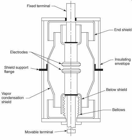
FIG. 1 Schematic of vacuum interrupter (Source: EPRI (2006)).
FIG. 2 Cutaway view of vacuum interrupter (Source: EPRI (2006)).
At contact separation, where the arc is supported by ionized gas in other interrupters, the arc in vacuum circuit breakers is supported by ionized metal vapors that are generated by the contacts themselves. Thus, at contact zero, vapor condensation and the collapse of ionization is almost instantaneous.
Outwardly, the vacuum interrupter appears to be the ultimate in switching devices that are independent of the operating system, as its breaking capability is dependent only on the material and geometry of the contact structure and the quality of the vacuum. This is not strictly true, however, because care has to be taken to ensure the correct travel and force characteristics of the operating mechanism with respect to the interrupter.
The high dielectric strength of the vacuum permits a small contact gap in the open position, typically 1/4-3/4 in. (0.64-1.9 cm). As a result of this fact and the low resistance of the metal vapor arc, the arc energy is very low.
Following arc quenching, most of the metal vapor condenses back onto the contacts and, by doing so, results in contact restoration; thus, contact erosion is extremely low.
At the moment of contact separation through which current is flowing, an arc discharge occurs. With currents approximating 10 kA, the arc burns diffusely on the whole contact surface between the contacts until the next current zero. Contact burn-off is low, as is the specific thermal load of the contact surface. For currents above 10 kA, the arc is severely pinched through the pressure of its own magnetic field. The concentrated burning arc occasioned by the high current density causes large amounts of contact material to vaporize very rapidly. The contact material, the shape of the contacts, and the manufacturing methods for the contacts play a significant role in the ultimate performance of a vacuum interrupter.
4. SF6 Circuit Breakers
Historically, the SF6 circuit breaker found its application in transmission systems, where it was a simpler alternative to the air blast circuit breakers that were used in the 1960s. The original circuit breakers were of the two-pressure type, where the contacts and arc control devices were immersed in a metal tank full of SF6, serving the dual purpose of an insulating and arc-extinguishing medium.
Essentially, the gas used for arc extinction was drawn out of the tank, then compressed and pumped into a separate small reservoir. With the opening of the circuit breaker, the compressed gas was discharged through nozzles around the contacts by a valve, resulting in the extinguishing of the arc.
In distribution systems, the first technique used in SF6 circuit breakers was that of a self-generated principle, referred to as the puffer system. This was a step toward simplifying the design with fewer moving parts.
Eliminating compressors, high-pressure seals, and heating elements obtained a much higher degree of reliability. The design did not, however, overcome the requirement for relatively long strokes and high operating forces, resulting in the need for powerful operating mechanisms with large energy output requirements. A quantity of SF6 gas is compressed with the commencement of a circuit-breaker-opening action prior to the separation of the arcing contacts. When the contacts part, an arc is drawn, and upon reaching current zero, the flow of gas rapidly cools the remaining plasma and sweeps away the arc products, leading to an extremely rapid increase in the dielectric strength of the gap, thus realizing a successful clearance.
An evolving design process developed self-blast interrupters, which use the arc energy to heat the gas and increase its pressure, allowing the gas to expand. This means that the pressure is raised by thermal means rather than by mechanical energy. It is a method that makes possible a lower-energy-operating mechanism than the puffer interrupter. The ensuing arc extinguishing process occurs in a similar manner to that of the puffer interrupters.
FIG. 3 illustrates this thermal expansion method. From the figure, the travel of the gas can be observed. When heated by large arc currents, the gas rapidly expands and pressurizes the upper vessel chamber. Pressure differential between the upper and lower vessel chambers creates a flow of gas, facilitating the cooling of the arc and the evacuation of the heat discharged by the arc. Thus, the gas flow effectively extinguishes the arc.
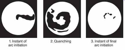
FIG. 3 Thermal expansion method (Source: EPRI (2006)).
The rotary arc quenching method shown in FIG. 4 is based on the interrupting current developing a rotating magnetic flux, which extinguishes the arc. Because the arc is rotated at approximately the speed of sound and is always exposed to the SF6 gas, extinction is ensured. The purpose of rotating the arc is to bring the intense heat of the arc column into contact with as much of the gas as possible, thus raising its temperature and, consequently, its pressure.
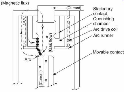
FIG. 4 Rotary arc quenching method (Source: EPRI (2006)).
By adopting the rotary arc and the thermal expansion method, a proportionate arc-quenching force is generated that is equivalent to the magnitude of the interrupting current. FIG. 5 represents a plot of arc-quenching performance versus interrupting current. From the curves, the comparative performance for the different interrupting techniques as a function of the interrupting current can be readily observed.
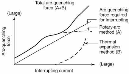
FIG. 5 Arc quenching performance versus interrupting current (Source:
EPRI (2006)).
With the advent of the latest technologies now available in SF6, the closing energy has been reduced to levels comparable to vacuum. This translates to fewer parts in the circuit breaker mechanism. In fact, the difference is so minimal that one European manufacturer of both SF6 and vacuum circuit breakers utilizes the same mechanism in each case.
5. Loss of Interruption Medium
Both sealed vacuum and SF6 interrupters are susceptible to the possible loss of their interrupting medium. Most users have shown a willingness to accept this susceptibility.
It should be noted that SF6 circuit breakers can be monitored in service, while no practical monitoring for commercial purposes is currently available for vacuum circuit breakers.
Sophisticated methods akin to those used in a laboratory are available, but economics make their use prohibitive.
For the SF6 circuit breaker, reliable pressure switches can be furnished within the circuit breakers poles, and these switches are wired into a two-stage alarm system to register any loss of the gas, facilitating action prior to a dangerous condition (Swindler, 1989). It should also be noted that, even with a total loss of SF6 gas, a 30-kV withstand level is maintained, and load currents can still be safely interrupted on a one-time basis (Swindler, 1993).
The mechanical connection into the gas bottle and the pressure switch itself are two more potential leak paths. The manufacturer's history of gas bottle leakage should be a factor in choosing the claim of a higher reliability in gas integrity.
Because SF6 gas is five times heavier than air, the possibility of some air replacing the SF6, even after the pressure has equalized, cannot be ruled out. However, a large proportion of air is needed to significantly reduce the breakdown strength, and designers account for this remote possibility by designing the open-gap contact system to withstand the service voltage at atmospheric pressure. This should be contrasted with a vacuum interrupter suffering a leak, where the voltage strength of the gap falls to a minimum level of a few hundred volts in the glow discharge region of 0.1-10 torr (13.3-133.2 Pa), recovering to around 30 kV/ cm at atmospheric pressure. When the vacuum is leaking and the voltage drops, failure is possible (Blower, 1986).
The consequences of attempted interruption of fault currents by a vacuum interrupter (with loss of vacuum) and by an SF6 circuit breaker (with loss of SF6) have not been adequately addressed in the available technical literature.
The following statement appears in a 1992 Doble Conference paper by a vacuum CB manufacturer:
For load currents in an ungrounded system, the vacuum circuit breaker carried the current and interrupted it satisfactorily.
In a 600 A grounded system, the phase in which the vacuum interrupter was at atmospheric pressure continued to arc for 15 seconds. All arcing was confined within the vacuum interrupter, although the envelope cracked. The SF6 interrupter at atmospheric pressure switched the load current in both grounded and ungrounded circuits. For 10 kA and at 25 kA the phase that had the vacuum interrupter at atmospheric pressure again continued to arc for 30 cycles until the backup circuit breaker interrupted the circuit. All arcing was confined inside the interrupter's envelope. In these experiments, the envelope showed no evidence of rupture. In fact, the only evidence of thermal stress to the ceramic envelope was some cracking.
The SF6 puffer interrupter interrupted the 10 kA current, but at 25 kA the SF6 did not interrupt the circuit and the continued burning of the arc caused the puffer to explode (Storms, 1992).
It should be noted that contemporary designs of both rotary arc and puffer SF6 circuit breakers employ an overpressure diaphragm at the bottom of each interrupter. In the event that the interrupter fails to interrupt owing to loss of gas, the diaphragm ruptures, directing the pressurized gas downward.
In early designs of SF6, problems were experienced with leaking seals. This is no longer the case with better contemporary varieties that use EP-type rubber O-rings. These O-rings have a longer life than the circuit breaker itself (FIG. 6). For all production runs, the leakage rate of gas is tested by highly sensitive detecting equipment that can detect leakage rate values up to .
FIG. 6 Relation between O-ring life and temperature (Source: EPRI (2006)).
6 Interrupting Ratings of Switching Devices
The most eminent reason for utilities to maintain or even reduce their fault current levels is to ensure proper functioning of circuit-interrupting devices such as circuit breakers and fuses. Interrupting capabilities of these devices will therefore be reviewed and provided in the guidebook.
Exceeding the interrupting rating will result in continued arcing, fire, explosions, and failure to interrupt the fault. Danger to any nearby personnel is likely. Damage to substation structure, switchgear, buses, and other equipment is also likely. Backup equipment must interrupt the fault.
7. Circuit Breakers
Circuit breakers in the United States are rated by the American National Standards Institute (ANSI) and the Institute of Electrical and Electronics Engineers (IEEE). Circuit breakers are classified by location, indoor or outdoor, and by voltage rating. Ratings for Class 1 circuit breakers, formerly classified as indoor circuit breakers, are shown in TABLE 1. Ratings for Class S2 circuit breakers, formerly classified as outdoor circuit breakers, are summarized in TABLE 2. Outdoor, high-voltage circuit breakers are summarized in TABLE 3. The maximum interrupting ratings for these various types are as follows:
• 63 kA for indoor distribution, 15 kV class
• 40 kA for outdoor distribution, 38 kV class
• 80 kA for outdoor transmission, 145 kV class.
TABLE 1 Typical Class S1 (formerly classified as indoor) Circuit Breakers for Cable Systems Rated Below 100 kV
TABLE 2 Typical Class S2 (formerly classified as outdoor) Circuit Breakers for Line Systems Rated Below 100 kV
TABLE 3 Typical Circuit Breakers Rated 100 kV and Above Including Circuit Breakers Applied in Gas-Insulated Substations
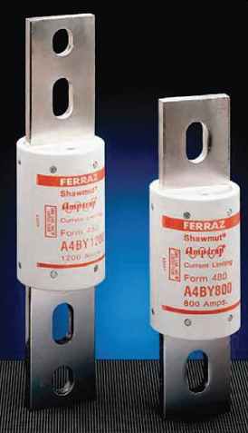
FIG. 7 Current-limiting fuses (Mersen).
TABLE 4 Preferred Ratings for Fuses
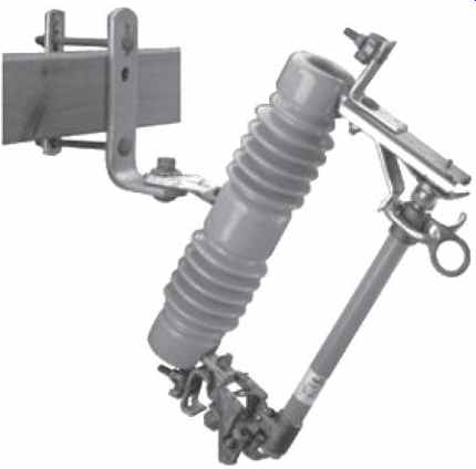
FIG. 8 Expulsion fuses are contained in a pole mounted fuse cutout (Cooper
Power Systems).
8. Fuses
There are two major types of fuses:
Current-limiting (FIG. 7) and expulsion type (FIG. 8). Fuse ratings are summarized in TABLE 4. While current-limiting fuses are enclosed in a sealed cylinder, and are usually contained in metal-enclosed switchgear, limiting the danger even if their short-circuit rating is exceeded, expulsion fuse links are mounted in open tubes on utility poles. These present several hazards when subjected to excessive short-circuit currents:
1. Exceeding the interrupting rating will result in continued arcing, fire, explosions, and failure to interrupt the fault.
2. Danger to public from falling arcing products if the fuse is on a pole along a street.
3. Damage to disconnecting switch, poles, enclosures, and other equipment is likely.
4. Backup equipment must interrupt fault, resulting in extended arcing time.
Current-limiting fuses generally have higher short-circuit ratings than expulsion fuses of the same size. Current-limiting fuses are available which fit in cutouts, replacing expulsion fuse links. Upgrading of expulsion fuses to current-limiting fuses and in general replacing fuses with units having higher interrupting ratings is the preferred solution to increasing available fault current levels.
9. Case Studies
These case studies describe the replacement of air-magnetic circuit breakers whose interrupting ratings have been exceeded with new SF6 or vacuum interrupters. Both of these cases are taken from nuclear power plants.
9.1 Example: Diablo Canyon
At Diablo Canyon (EPRI, 2003), the prime motivation for upgrading air-magnetic circuit breakers to SF6 was an increase in the fault level and the elimination of a potentially hazardous design issue rather than the desire to save maintenance and other costs. Beginning in March 1994, a dedicated user team set out to evaluate the various options available. The team had extensive experience in preparing the type of quality assurance (QA)/dedication requirements that were to be imposed on the selected vendor for this project. The project consisted of 110 units.
Maintaining the existing switchgear to provide a 350-MVA circuit breaker within the same footprint as the 250-MVA design necessitated a compact circuit breaker design. At the time, only one circuit breaker met this criterion.
Others did not represent completed, tested designs. The fact that this element was SF6 provided additional comfort because the user preferred monitoring the state of the interrupting medium and desired a surge-free performance. These criteria in conjunction with the QA requirements stipulated by Pacific Gas and Electric were the defining characteristics in selecting the vendor for this particular project.
The Diablo project is a useful model for the nuclear industry for converting circuit breakers as the combination of high seismic levels, the qualification/dedication complexities, and the technical challenges are clearly defined.
The significant lessons learned from this project fall into two distinct areas that are unique to the nuclear environment. The first area concerns how to administer an adequate nuclear QA program in the dedication and building of circuit breaker conversions without losing sight of the primary mission of building reliable conversions in a timely and efficient manner.
Many of the issues associated with the manufacturing process arose because of the intrusive nature of implementing the QA program. Careful consideration of QA needs was balanced with the requirements of a production facility that is geared to the non-nuclear aspects of building conversions.
The second area concerns the interface of the new design with the existing cubicles and the flexibility to undertake essential changes to cubicle interlock interfaces while being cognizant of nuclear constraints on the design of the conversion.
A further example of flexibility relates to a deviation in testing procedures. There is no economical method to field test the pressure switches contained within the poles of an SF6 circuit breaker. After numerous meetings and detailed design reviews of the product and its associated manufacturing methods, acceptance was sanctioned as the lesser of two evils - in other words, accepting the pressure switch factory reliability test results and the track record of the product in the field as opposed to the incorporation of a vacuum element, which cannot be monitored.
To the users, this project is a success. A replacement circuit breaker was effectively integrated into the existing plant power system, significantly increasing fault protection and ensuring a considerable maintenance cost savings over the circuit breaker's installed life.
9.2 Example: Dresden and QuadCities
There were several factors involved in the decision-making process at the Dresden and Quad Cities plants (EPRI, 2003). These factors extended from the problems associated with obsolescence and lack of spare parts; the required addition of cubicles; the need to upgrade interruption levels; the objective of minimizing outage duration during modifications; and recognition of the state of the 20-year-old motors, transformers, and cables.
Initially, wholesale removal and replacement of the switchgear, with the inclusion of additional cubicles, was considered. The original equipment manufacturer (OEM) was favored in order to maintain continuity of products and maintenance services. The preferred technology was air magnetic because of its established acceptable overvoltage response, but this medium was no longer available from the OEM.
The costs for the subject proposal of full switchgear replacement were judged excessive given the extensive rigging effort, necessary extension in outage time, and the risk of damage to the old power and control cables (Shah et al., 1988; Dinkel, Watts, and Langlois, 1986; Fish, 1994; Heath, Freeman, and Cochran, 1987). This can be readily appreciated in recognition of the fact that the total number of existing cubicles was 100 and 12 additional units had to be accounted for.
An alternative approach based on the concept of a 250-350 MVA conversion circuit breaker that would fit into the existing 26-in.-wide cubicle seemed appealing, as it became apparent that it was economically attractive and would eliminate the considerable risks pertaining to full replacement. At the time, IEEE Standard C37.59 was in draft form and could serve well as a guide for the planned scope of work.
The final selection of vacuum or SF6 circuit breaker technology was made on the basis of cost, after factoring in the associated costs for surge arresters, spare parts, training, and vendor services. It was originally assumed that the existing 250 MVA bus rating was insufficient to withstand the 350 MVA momentary ratings. Testing in a high-power laboratory proved otherwise, and the approximately 20-year-old cubicle with its 20-year-old bus and bracing successfully withstood the momentary test stresses. This certification allowed the project to abandon the time-consuming and expensive change-out of the existing bus bracing.
10. Low-Voltage Circuit Breakers
Low-voltage circuit breakers are operated at or below a nominal voltage of 1000 V AC or DC (IEEE, 1993). These can be classified into several types:
1. Power Circuit Breakers (LVPCBs) (FIG. 9). A power circuit breaker is capable of making, breaking and carrying high fault currents for a specified time. Because they can carry a high current for a specified period of time, LVPCBs may be set up to operate with a short time delay tripping function, without an instantaneous trip.
This property is helpful in coordinated systems, such as in main-tie-main Switchgear. However, the short time delay will increase the arc flash hazard due to the longer arcing time. LVPCBs generally are constructed on a metal frame. They are repairable, and all can be disassembled and refurbished when required.
2. Insulated-Case Circuit Breakers (ICCBs) (FIG. 10). ICCBs are capable of making and breaking high fault currents, but are not rated to carry them for a specified time.
Thus, ICCBs are required to have an instantaneous trip function. ICCBs are usually constructed with enclosures of insulating materials and only selected components can be replaced.
3. Molded-Case Circuit Breakers (MCCBs) (FIG. 11). MCCBs are assembled as an integrated unit enclosed in a molded insulating (plastic) housing. MCCBs are capable of making and breaking high fault currents, but are not rated to carry them for a specified time. Thus, MCCBs are required to have an instantaneous trip function.
MCCBs are not repairable, and must be replaced if they fail.
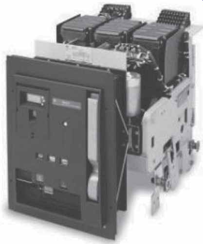
FIG. 9 Low-voltage power circuit breaker (General Electric Company).
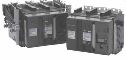
FIG. 10 Low-voltage insulated-case circuit breakers (General Electric
Company).
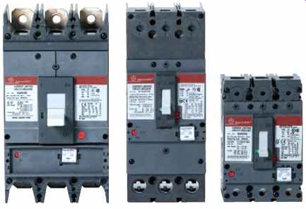
FIG. 11 Low-voltage molded-case circuit breakers (General Electric Company).