AMAZON multi-meters discounts AMAZON oscilloscope discounts
[Note: various equations, denoted by "e." are not yet avail., but coming soon.]
1. Introduction
The design of safe electrical systems relies not just on reducing hazards present from energized conductors in terms of shock and arc flash, but in rapidly de-energizing conductors whose operation presents a safety hazard. For example, if an overhead line conductor or insulator is broken and a short circuit to the earth occurs, presenting a severe safety hazard to any person in the vicinity, a fuse or circuit breaker must be present to interrupt and clear the fault as soon as possible (usually milliseconds) thus greatly reducing the hazards presented. These protection systems, which both detect and clear faults, must themselves be able to operate reliably and effectively, under conditions of high electrical stress, not only the elevated currents caused by short circuits but also the overvoltage transients which may be present as well. This section will deal with the effects of high fault currents, while voltage transients will be covered in a later section.
The literature on effects of high fault currents on protection and metering equipment will be reviewed. The capabilities and limitations of existing short-circuit protection devices will be included in the literature search. High fault currents are well known to cause saturation of iron core current transformers (CTs). This can adversely affect the performance of system protection devices. High fault currents can also exceed the range of operation of current-operated protective devices and produce high voltages in the CT secondary circuits. This section is adapted from EPRI (2006).
The National Electrical Code (NEC) (NFPA, 2014), Article 110.9, requires that "Equipment intended to interrupt current at fault levels shall have an interrupting rating at nominal circuit voltage sufficient for the current that is available at the line terminals of the equipment." No exception exists for contingencies such as when the fault current level only exists for a short time owing to switching or other operations. For example, a double-ended lineup of 15 kV switchgear, with a normally open tie circuit breaker with a closed transition has to be rated for the higher short-circuit duty which occurs when the tie breaker is closed. This approximately doubles the fault level and increases CT saturation, both AC and DC.
IEEE Standard C37.110-2007, IEEE Guide For The Application of Current Transformers Used for Protective Relaying Purposes (IEEE, 2007b) provides recommendations for calculations for AC and DC CT saturation.
The performance of protective relaying systems in the presence of CT saturation has been discussed in, among others, IEEE standards (IEEE, 2007b), textbooks on relaying (Blackburn, 1998; Elmore, 1994), and IEEE committee reports (Linders et al., 1995) (Power Systems Relaying Committee, 1976). Despite the great amount of previous work, this topic still causes great controversy and universally accepted application guidelines do not yet exist.
2. Current Transformer Saturation
CTs are connected in series with the circuit whose current is to be measured as shown in FIG. 1, (EPRI, 2004b).
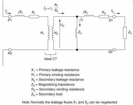
FIG. 1 Current transformer equivalent circuit (Source: EPRI, 2006).
CTs are intended to deliver a secondary current that is directly proportional to the primary current with as little distortion as possible. In most cases, the secondary output current is usually reduced to less than 5A. Although there are CTs with 1A or 10A secondaries, the most common rating in the United States is 5A.
CTs are rated for a certain turns-ratio of operation. For example, a CT with a turns-ratio of 500 : 5 reduces 500 A on the primary to 5 A on the secondary. A properly designed CT circuit yields a secondary current of 5 A or less at rated primary current. Although the CT secondary and the relay are not intended for continuous operation at higher than 5 A, they are designed to withstand greater values of current for short periods. For example, short-circuit currents may be 20 or more times the normal current in a power system.
During normal operation, the CT secondary winding induces a magnetic flux that opposes and nearly cancels the primary induced flux. As a result, the flux density is very low and the resulting voltage at the secondary terminals is also very low. Relays, meters, or other connected devices are constructed with only a few turns of relatively large wire-this low impedance effectively functions as a short circuit across the CT secondary. The secondary voltage of a CT remains at a low value as long as the secondary circuit remains closed. An open circuit on the secondary side of a CT that still has current flow on the primary side can result in a dangerously high secondary voltage.
Opening the secondary removes the opposing secondary flux, thus allowing the primary flux to generate a very high voltage at the secondary terminals. Electrical arcing caused by an open-circuited CT can injure personnel and damage equipment. When the primary side is carrying any current, great care must be taken to ensure that the secondary circuit remains closed at all times.
The CT's ability to produce a secondary current proportional to its primary current is limited by the highest secondary voltage that it can produce without saturation. Beyond a certain level of excitation (actual values are readily available from the manufacturer), the CT is said to enter saturation. When saturated, most of the primary current maintains the core flux, and the shape of both the exciting and secondary currents departs from the normal sine wave. The secondary voltage and current then collapse to zero, where they remain, until the next primary current zero is reached. The process is repeated each half-cycle and results in a distorted secondary waveform.
Saturation of a CT can prevent a protective relay from operating properly. For this reason, a CT must be carefully sized so that it will perform properly for the maximum expected fault current. Low-ratio CTs (e.g., 50 : 5 or 75 : 5) are particularly susceptible to saturation during fault conditions.
The following problems may exist if a CT is allowed to saturate:
False tripping. Differential relays used for transformer protection may respond to a through-fault condition. Numerical relays, however, pose far lower burden (0.5 VA) on CTs. Numerical relays are capable of detecting CT saturation and blocking the relay from tripping, minimizing the effect of false tripping.
Delayed tripping. A distorted secondary reproduction of the primary current can delay relay time response. This delay in tripping may result in de-energizing a larger portion of the system due to loss of relay coordination caused by the CT saturation.
Failure to trip. Failure to trip may occur if the CT secondary current is very low or extremely distorted. Backup relays must then respond to clear the fault. Digital relays, however, have the added advantage that they can detect these conditions and still deliver a trip because the relay is not dependent on the power that must be supplied by the CT to trip.
3. Saturation of Low-Ratio CT
High levels of fault current, especially when DC offset is present, cause the secondary current of a CT to be significantly distorted and diminished in magnitude, even with a very small burden. This is most significant with low-ratio CTs. CT saturation may cause overcurrent relays to misoperate or fail to operate, resulting in a failure of the protection system.
3.1 AC Saturation
AC saturation is a gradual process, whereas the rms value of the current increases and the ratio accuracy of the CT decreases. AC saturation begins to affect protective relay performance if the rms excitation voltage begins to exceed the "saturation voltage," where the rate of increase of the excitation current with respect to excitation voltage greatly increases. According to the definition given in the standard, the "saturation voltage," VX, is the point of intersection of lines extended from the straight portions of the saturation curve. This is usually slightly higher than the "knee-point voltage," which is defined in the standard as the point on the saturation curve where a tangent drawn to the curve has an angle of 45° to the horizontal axis. See the illustration of the knee-point concept in FIG. 2.
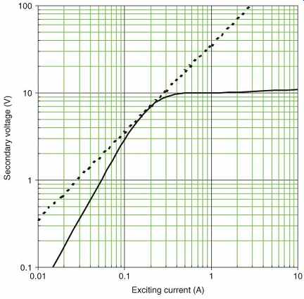
FIG. 2 The "knee point" of a CT saturation curve is the point
where a tangent to the curve forms a 45° angle with the horizontal axis (Source:
EPRI, 2006).
Section 4.5.3 of IEEE Standard C37.110-2007 (IEEE, 2007b) suggests that the effective CT ratio error will be significant if the calculated secondary voltage that the CT must support exceeds the saturation voltage, , that is, 11.1
…where…
= CT secondary voltage
= CT secondary current
= CT primary current
N = CT turns ratio, and
= total secondary burden of the CT.
After an example calculation of this type, where approaches , one author states, "Although this is near the knee of the saturation curve, the small excitation current does not significantly decrease the fault current to the relays.".
Another commonly used criterion is from Section 5.10 of the standard, "A rule of thumb frequently used in relaying to minimize the CT saturation effects is to select a CT with a C voltage rating at least twice that required for the maximum steady-state symmetrical fault current." It is furthermore stated in (Linders et al., 1995) that "One basic rule-of-thumb has applied in the application of CT's, namely, The knee-point voltage of the CT as defined by the CT excitation curve should not be less than twice the voltage required to drive the maximum secondary symmetrical current through the combined burden of the relay, connecting wiring and CT." The "C" rating is often assumed to be approximately equal to the knee-point voltage, in fact, "the knee-point voltage may be 50-75% of the standard accuracy class voltage rating of the CT (e.g., C400)." (IEEE, 2007b, Section 4.5.3).
It is important to carefully consider the implications of AC saturation before applying these criteria. As stated above, the effect of AC saturation is to cause an error in the effective ratio of the CT such that the secondary current available to relays and other measuring devices will be less than what would be expected knowing the primary fault current and the nominal CT ratio. The fact that the calculated voltage exceeds the saturation voltage, , does not mean that the CT collapses entirely-it is just that the ratio error increases significantly.
There is more to saturation that an increase in the effective ratio error of the CT. The presence of significant saturation also causes the waveform of the secondary current to depart from the normal sinusoidal pattern. Hence, when significant saturation is present, it is no longer possible to think in terms of conventional sinusoidal response.
Practically, an accurate measurement of current is only important in the case of time overcurrent relays. With instantaneous relays, it is only important to know that the available current will be greater than the setting of the relay. It is not important to know by how much the available secondary current will exceed the instantaneous relay setting or whether the waveform of that current will be a respectable sinusoid.
Therefore, the pertinent question is, "Given the performance characteristics of the CT and the associated CT burden, will the CT be 'reasonably linear' for all fault magnitudes for which the time overcurrent relay is expected to operate?" On the basis of this perspective, the following conditions should be checked:
For feeder relays having both time and instantaneous elements, will the calculated secondary voltage be less than the CT saturation voltage, , for the maximum fault at which the time overcurrent relay is expected to operate, namely, the current level at which the instantaneous element is calibrated to pick up?
For main and tie relays with no instantaneous elements, will the calculated secondary voltage be less than the CT saturation voltage, , for the maximum fault at which the time overcurrent relay is expected to operate, namely, the expected (calculated) maximum current through the circuit breaker associated with the CT in question?
3.2 DC Saturation
The standard (IEEE, 2007b) suggests two criteria regarding DC saturation. The first (Section 4.5.3) is that the effective CT ratio error will be significant when the following condition is met:
eq.2
…where…
= resistive component of the CT burden
X = primary side system reactance, and
R = primary side system resistance.
Alternatively, one author (Elmore, 1994. p. 80) suggests that if...
eq.3
DC saturation will not occur. If remanence is ignored, these two equations may be simplified as representing eqn.4 for equation (2) and eqn.5 for equation (3).
These equations may be seen in some CT application calculations and are valid as long as there is no significant inductance in the CT secondary circuit or significant remanence in the CT itself. Dropping the factor of 1 in equation (4) simply means that is assumed to be high.
Remanence is the tendency of the iron core of a CT to retain magnetic flux on the basis of prior history. Remanence flux levels of up to 80% of saturation level have been observed (IEEE, 2007b, par. 4.6.1). The worst case for remanence comes about when a DC continuity test is used to verify CT circuit continuity (Seveik and DoCarmo, 2000), but this remnant flux will dissipate if the CT is demagnetized following the test.
A more common issue comes up when the circuit breaker interrupts an offset fault current. Interruption of the DC component of this current leaves one or more CTs partially magnetized. This remnant flux will also dissipate with a few seconds of loading, if 60% of the saturation voltage is exceeded, but it can be a concern if the breaker subsequently recloses into a fault before flux dissipation can occur.
Remnant flux may either aid or oppose the magnetization imposed by DC transients.
Practically, remnant flux is not a real concern in industrial applications where there is no automatic reclosing.
DC saturation does not occur instantaneously, but rather builds up with time. Hence, the second criterion to be considered in evaluating DC saturation is the time to saturate (in fundamental frequency cycles):
eqn.6
The saturation factor KS, is defined as:
eqn.7
This formula does not include the effect of remanence, which will decrease the time to saturation.
The effect of DC saturation is to interfere with operation of instantaneous relays. Given the performance characteristics of the CT and the associated CT burden, will DC saturation occur quickly enough, and with sufficient severity, to interfere with the operation of these instantaneous relays? On the basis of this perspective, the following tests should be performed:
For feeder relays having both time and instantaneous elements, will the calculated secondary DC saturation voltage be less than the CT saturation voltage, VX, for the maximum fault at which the instantaneous relay is expected to operate, namely, the maximum available fault current and will the "time to saturate" be shorter than the time required for the measuring algorithm in the instantaneous relay to respond to the CT secondary current prior to the point at which significant DC saturation appears (typically, one-half cycle)? For main and tie relays with no instantaneous elements, DC saturation is not an issue.
If the effect of remanence flux is taken into account, all relay-CT combinations may have time to saturation of less than one cycle, effectively preventing relay operation. This situation is typical of most applications of overcurrent relays with CTs in medium-voltage switchgear. It is a generally accepted compromise that non-operation of overcurrent relays may occur when the remanence flux is large. For this reason, backup overcurrent protection and bus differential protection, which are not susceptible to CT saturation, are utilized in power systems where DC saturation may be a problem, such as in generating stations. IEEE standard C37.110-2007 (IEEE, 2007b, Section 4.5.3) states, "These requirements generally result in impracticably large CTs, and hence compensating steps must be taken to minimize saturation effects on the relay protection plan. Some high-speed instantaneous relays can operate before saturation has time to occur." In many existing relaying systems, the time-overcurrent relay functions serve to back up the instantaneous relay functions. It is the instantaneous functions that may be susceptible to DC saturation. Because the formulae are based on certain assumptions, there is an error of -0 + 0.5 cycles in the time to saturation. The actual response of the relay to the saturated current waveform, FIG. 3, is subject to many imponderables. An answer to the question of whether a particular instantaneous relay will respond within an acceptable time delay can only be answered by test.
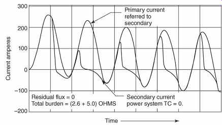
FIG. 3 Typical waveforms of CT primary and secondary current with DC
saturation (Power Systems Relaying Committee, 1976) (c) 1976 IEEE.
The instantaneous relay may operate immediately if the time to saturation is long enough to allow it to operate. If the time to saturation is too short, the relay may operate several cycles later when the CT emerges from saturation. The maximum delay for instantaneous tripping is determined by the coordination time intervals (CTIs) defined for the protective system.
4. Testing of Current Transformer Saturation
When testing a specific CT for application in a particular situation, the tests should model the CT secondary circuits with the identical lead sizes and lengths. The tests should be conducted in a three-phase high-current short-circuit laboratory using system primary current and ratios as determined from the short-circuit study. Tests should be made with all relays attached to the CT using maximum existing system settings. Tests should be made both with and without the overvoltage protective devices (OCPs) (surge suppressors) used on the CT secondaries. A typical test setup is shown in Figures 11.4 and 11.5. If the time to close the instantaneous contacts is less than the defined maximum time, the CT-relay combination will be deemed to have passed the test. If a relay fails the test with standard accuracy CTs, the test shall be repeated with high accuracy CTs. The CTs to be used if further tests fail are the next higher ratio standard and high accuracy units. The first CT-relay combination which passes the test should be utilized in the system.
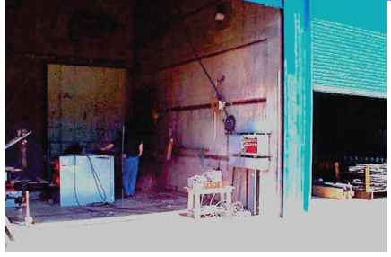
FIG. 4 View of a test setup located in test cell.
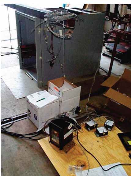
FIG. 5 Relay shown connected to a test setup. OCP modules shown immediately
to the right.
Some protective relays contain an "overreach filter" which removes the DC component from an asymmetrical current wave. This will slow the response time by 10-15 ms (0.6-0.9 cycles).
DC saturation occurs in the core of the CT and affects the current waveform that is input to the relay. The use of an overreach filter will not prevent DC saturation but will reduce the probability of tripping by inserting an additional time delay in the relay response. The use of the overreach filter on the relays is not recommended in this application. Actual tests should be performed with and without overreach filters (if present).
The paper "Relay Performance Considerations with Low Ratio CT's and High Fault Currents" (Power Systems Relaying Committee, 1976) stated that in order to eliminate CT saturation, the secondary circuit voltage should be less than ½ the knee voltage. Testing would be performed to prove which of the CTs under evaluation would be required as a minimum to operate the relay.
The effects of DC saturation should also to be evaluated during testing.
The CTs to be used were to be short-circuit tested with maximum three-phase fault with maximum offset. A test is considered successful if one of the two relay operations occurred: either the instantaneous or the overcurrent function operated. Three successful sequential tests have to occur for a CT to be considered acceptable.
Also unknown are effects of OCPs. If any test failed, the OCP was to be removed and the test performed again. If the test was successful after the OCP removal, then all OCPs should be removed.
Three-phase testing is performed at a specified ratio to verify that the instantaneous function of all relays will operate within required limits when using standard accuracy class CTs. Line-to-line testing could be used to prove that each relay's instantaneous function would not have operated with standard accuracy class CTs.
A test cell typically provides fault current directly to the test setup from a generator at a specified level of fault current, in kiloamperes, and ratio. A sample of typical test current is shown in FIG. 6.
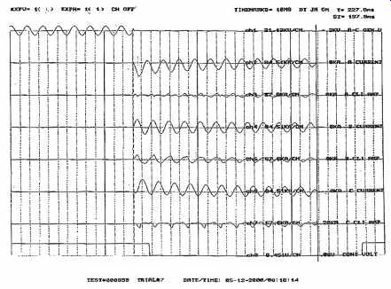
FIG. 6 Example test report for CT saturation (Source: EPRI (2006)).
According to the equation for the test current ( Blackburn, 1998):
The DC time constant, , affects the rate of decay of the DC component of the fault current.
This time constant is controlled by the time constants of the generator and the series reactor.
It is difficult to reach firm conclusions from this data. However, the following tentative conclusions may be reached:
1. The minimum criterion to avoid AC saturation is that the maximum CT secondary voltage should be less than the so-called "knee-point" voltage or approximately the accuracy classification ("C" rating) voltage.
2. There is a conflict between the recommendations of the standard (IEEE, 2007b) and paper (Linders et al., 1995) regarding whether 50% or 100% of the knee-point voltage should be compared with the maximum CT secondary voltage.
3. The criteria to avoid DC saturation of having the maximum CT secondary voltage times the ratio of the faulted circuit be less than the knee-point voltage is unrealistic in most instances. Owing to the lack of a better guideline, it is recommended that disputed CT-relay combinations be tested.
4. Because of the issue of unequal DC offset of various phases raising doubts about the validity of testing of three-phase relays, phase-phase fault testing is recommended instead of three phase fault.
5. The issue of whether remnant flux is significant in industrial applications should be investigated further.
6. In the saturation calculations shown above, by far the greatest burden problem is the CT. The use of solid-state relays reduces the burden problem to only a small extent compared to the burden of the CT. Further efforts should be made to provide new CT designs, which reduce this burden.
7. Be very careful of source limitations when testing, that is, higher may not necessarily be better as imbalance effects may be more prominent. It is better to match the testing requirements to what you actually need. Be sure and get in advance the characteristics of the source from the testing facility (if you can) well before testing begins.
8. Since testing facilities are expensive, have all your calculations prepared and checked.
9. Be familiar with the programming of the relays prior to the testing as this saves time.
10. Use relays with waveform capture and event log capture. This is invaluable for analysis.
11. Bring a digital camera. It helps in keeping track of the testing setup.
12. Get as many results as possible on paper before to leaving the test facility for analysis purposes as it can take some time to obtain these results officially.
5 Effect of High Fault Currents on Coordination
The protective device coordination in a radial feeder or for any distribution feeder is important. The coordination of protection devices is necessary to maintain selectivity (i.e., to remove the portion of the power system that is experiencing the fault). The inverse-time-current curve provides coordination at the same time that it offers the speed and accuracy needed to clear and the correct fault quickly. By the nature of the design, the inverse-time curves utilize the magnitude of the current to decide the tripping time, unlike the instantaneous relays with definite time.
The name of the inverse-time curve is self-explanatory. The higher the magnitude of the fault or the load current, the less time is required for the relay to operate. This provides quick removal of the faulted portion from the power system. Under normal load condition or for a low-magnitude fault current, the relay allows enough time for other downstream devices to clear the fault. Because the microprocessor relay has to process the current mathematically to decide the time to trip, the relay can be equipped with different types of inverse curves.
The user at the time of the study decides the curve to be used. The relay simply actuates that curve equation and processes accordingly. IEEE has created standard inverse curves (IEEE, 1997). The manufacturer of the microprocessor relay must comply with these curves.
Depending on the time to trip for higher current or for lower current, different curves are available.
The following list includes a few of the many popular curves:
1. Moderately inverse
2. Inverse
3. Normally inverse
4. Very inverse
5. Extremely inverse
The curves for the moderately inverse, very inverse, and extremely inverse curves are set forth in (IEEE, 1997):
Moderately inverse:
eqn.9
Very inverse:
eqn.10 Extremely inverse:
eqn.11 FIG. 7 depicts the three of these curves plotted according to the equations set forth by IEEE.
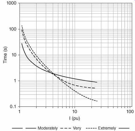
FIG. 7 IEEE inverse-time overcurrent curves; time dial set at the midpoint.
An example of miscoordination of a feeder circuit with a fault current increase is shown in FIG. 8, where Fuse 1 clears fault F1 before the relay operates. The coordinating time interval (CTI) T1 is sufficient. The fault current increases beyond design value T2 < CTI. The breaker opens at the same time as Fuse 1, causing a wider outage.
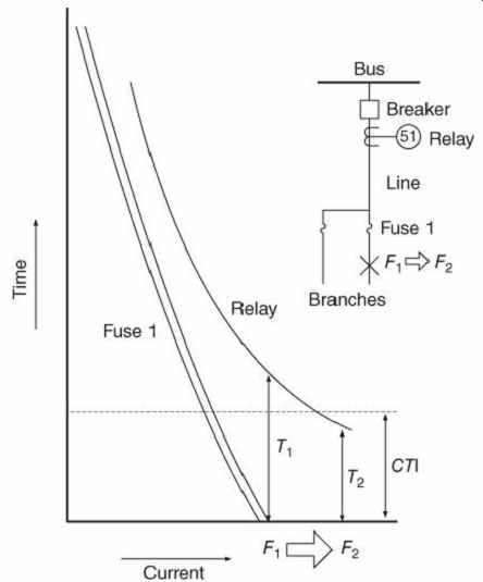
FIG. 8 Coordination of a distribution feeder (Source: EPRI (2006)).
6. Protective Relay Ratings and Settings
Protective relays (EPRI, 2004b) have a reputation for providing reliable service for many years. Nonetheless, electromechanical protective relays are delicate instruments that are susceptible to the degradation of components that may affect performance.
Owing to their design, numerical relays, FIG. 9, have eliminated the degradation that can be expected from the mechanical components of electromechanical relays, FIG. 10.
Numerical relays also use minimal electronic components when compared to electronic relays. The failure of a protective relay to contain and isolate an electrical problem can have severe plantwide repercussions. When an expected protective action does not occur, the end result of an electrical abnormality may be catastrophic equipment damage and prolonged downtime instead of localized minor damage.
Because of the severe consequences of a failure, protective relays should be maintained in a high state of readiness. Critical applications should be carefully evaluated for redundant protection.
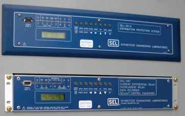
FIG. 9 Numerical protective relays.
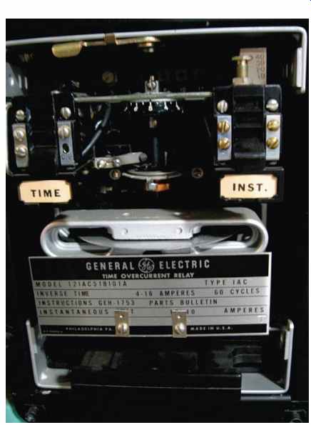
FIG. 10 Electromechanical protective relay.
Protective relaying is an integral part of any electrical power system. The fundamental objective of system protection is to quickly isolate a problem so that the unaffected portions of a system can continue to function.
Protective relays are the decision-making device in the protection scheme. They monitor circuit conditions and initiate protective action when an undesired condition is detected.
Protective relays work in concert with sensing and control devices to accomplish this function.
There are several reasons to use protective relaying:
1. To provide alarms when measured process limits are exceeded, thereby allowing operators an opportunity to intervene with corrective actions.
2. To isolate faulted circuits or equipment from the remainder of the system so that the system can continue to function.
3. To limit damage to faulted equipment.
4. To minimize the possibility of fire or catastrophic damage to adjacent equipment.
5. To minimize hazards to personnel.
6. To provide post-fault information to help analyze the root cause.
Under normal power system operation, protective relays remain idle and serve no active function. However, when required to operate because of a faulted or undesirable condition, it is imperative that the relays function correctly.
Another point of concern is the undesired operation of a protective relay during normal plant conditions or tolerable transients.
Inadvertent relay operation can result in unnecessary system or plant downtime. A maintenance and surveillance program will help to ensure that the protective relays respond properly to normal and abnormal conditions. This frequency of testing can be extended to longer periods than in electromechanical devices. The number of tests can also be reduced owing to the design and construction of the relays. An effective maintenance program for protective relays accomplishes two primary goals. First, it provides a high degree of confidence that the electrical power protection system will respond to abnormal conditions as designed. Periodic assurance that protective relays are in an operable status is particularly important. Relay problems are generally detected by internal test routines and during operational checks via a human machine interface (HMI). Secondly, an effective maintenance program preserves the relay's readiness and helps to counteract normal and abnormal in-service deterioration that can affect a relay's electronic components over time. Even under normal conditions, electrical, thermal, and environmental stresses are continually at work, slowly degrading the relays. This deterioration is much slower in numerical relays than in electromechanical relays because numerical relays are not affected by mechanical deterioration. Routine maintenance checks help to identify any deterioration in the device. The life of numerical relays cannot be prolonged by recalibration, cleaning, and general maintenance because numerical relays are either functional or not. Failed devices must be removed, repaired, and/or replaced. Failed devices or device components such as printed circuit boards should be sent to the supplier for repair.
7. Effects of Fault Currents on Protective Relays
Numerical relays contain sensitive electrical components that are designed to operate at specific values of voltage and current. Voltages range from 110-480 VAC and 24-250 VDC.
Currents are provided in either 1A or 5A (AC) rating. The maximum design-rated voltage is the highest rms alternating voltage or direct voltage. The maximum current is the highest rms alternating current or direct current. These maximum values are the limits at which the relay can operate continuously.
The operating coils of older electromechanical and solid-state relays typically determined the relay's rating. Today, numerical relays are supplied with multiple range or universal power supplies and binary inputs/outputs that operate at specific voltages that are set by using internal links or jumpers in the relay. The current and voltage sources can also have multiple operating ratings. Relays can be provided with secondary current selections of 1 or 5 A.
Secondary voltages to the relay can be configured for a range of voltages and can typically be connected wye or delta by a setting parameter rather than a hardware configuration. Voltage inputs can be configured for phase-phase or phase-ground.
Relay burden is greatly reduced with the use of numerical relays. The power consumption of numerical relays can be expected in the 0.04-0.10 VA range. This means that in many applications, the relay burden is negligible. In older applications where the relay burden was much higher, intermediate CTs may have been required. Numerical relays normally no longer require these intermediate transformers.
Thermal overload capacities are also higher.
For example, the effective thermal overload can reach a rating of 500 A (1 s) and a dynamic rating of 1250 A (half-cycle).
7.1 Examples
1. Electromechanical Relay (GE Multilin, 1997) GE IAC53 1.5-12 A time overcurrent taps;
instantaneous range: 10-80 A; continuous current rating of the time overcurrent unit:
10-30.5 A; short-time current rating of the time overcurrent unit: .
For example, with a 500 : 5 CT, 26 kA of fault current for 1 s will reach the thermal limit of this relay.
2. Digital (Schweitzer, 2003) SEL351 0.5-16 A time overcurrent range; instantaneous overcurrent range 0.25-100 A on 5 A CT; limits: 15 A continuous; 500 A @ 1 s, linear to 100 A; 1250 A @ 1 cycle.
For example, with 500 : 5 CT, 50 kA of fault current for 1 s is the limit.
8. Methods for Upgrading Protection Systems
8.1 Update Short-Circuit Study
In order to obtain complete coordination of the protective equipment applied, it may be necessary to obtain some or all of the following information on short-circuit currents for each node or bus:
1. Maximum and minimum momentary (first cycle) short-circuit current.
2. Maximum and minimum interrupting duty short-circuit current.
3. Maximum and minimum ground-fault current.
The momentary currents are used to determine the maximum and minimum currents to which instantaneous and direct-acting trip devices respond. The maximum interrupting current is the value of the current at which the circuit protection coordination interval is established.
The minimum interrupting current is needed to determine whether the protection sensitivity of the circuit is adequate.
The short-circuit study and coordination study should be updated when the available short circuit of the source to a plant is increased.
8.2 Update Protective Device Coordination Study
The objective of a coordination study is to determine the characteristics, ratings, and settings of overcurrent protective devices to ensure that the minimum unfaulted load is interrupted when the protective devices isolate a fault or an overload anywhere in the system.
At the same time, the devices and the settings selected should provide satisfactory protection against overloads on the equipment and should interrupt short-circuit currents as rapidly as possible.
The coordination study provides data useful for the selection of instrument transformer ratios, protective relay characteristics, and settings and fuse ratings. It also provides other information pertinent to the provision of optimum protection and selectivity in the coordination of these devices. When plotting coordination curves, a certain time interval must be maintained between curves of the various protective devices in order to ensure correct sequential operation of the devices. This interval is called the coordination time interval.
When coordinating inverse curves, the time interval is usually 0.3-0.4 s. This interval is measured between relays in series at the instantaneous setting of the load side of the feeder relay or maximum short-circuit current which can flow through both devices simultaneously.
A basic understanding of time-current characteristics is essential in any study. Initial planning and power system data are also essential for any coordination study.
The initial planning process should include the following activities:
1. Develop a one-line diagram.
2. Determine the load flow.
3. Collect data.
4. Conduct a short-circuit study.
5. Determine time current coordination curves for all the devices in the system.