AMAZON multi-meters discounts AMAZON oscilloscope discounts
- Introduction
- Gas Discharge Lamps and High Intensity Discharge Lamps
- Introduction to Ballasts
- Some Definitions and Evaluation of Performance
- Conventional Ballasts
- High Frequency Resonant Ballasts
- The Next Generation of Ballasts
- Power Factor Correction and Dimming Ballasts
- Comparison of Compact Fluorescent Lamps Using Magnetic and Electronic Ballasts
- Future Developments of Electronic Ballasts
- References
1 Introduction
Ever since the first energy crisis that the world faced during 1970s (due to a sudden and unexpected rise in the price of petroleum fuel), the electricity industry has been trying to meet the world's burgeoning energy needs by building more power plants that don’t depend on oil or by looking for other non-conventional energy sources such as solar power. During the 1990s, however, a new concept called "negawatts"--the idea that the investment in energy conservation will often yield higher returns than investment in new power stations--is gaining popularity.
According to this view the electricity demand could be limited by matching an appropriate and efficient technology to each energy utilization task.
Electric lamps are a case in point. A century after its invention the electric filament lamp is still one of the world's most popular ways of providing artificial illumination in industry as well as in households, despite the fact that the filament lamp yields comparatively the least light output for a given amount of electrical energy input. This figure known as the luminous efficiency or efficacy, hardly has been improved by any new technology as far as the filament lamp is concerned.
The other most popular source of electric lighting is the fluorescent lamp which uses the principle of an electric arc discharge through a gas at a low pressure to produce visible light. The illumination by the principle of gas discharge has been in existence for more than fifty years and almost all new research and development in the area of improving efficacy of lighting has been concentrated broadly on the fluorescent lamp technology. For instance, it has been estimated in the United States that the fluorescent lamps produced by a factory which costs eight million dollars to build will save electricity worth of one billion dollars, equivalent to the cost of a 700MW power plant.
Thus the phrase "energy saving lamps" is basically synonymous with the new technology being developed for the improvements in fluorescent lamp technology.
Particularly, the development of low-wattage fluorescent lamps together with highly efficient electronic ballasts (the auxiliary circuit required to control the operation of a gas discharge lamp) is the main focus of the lighting industry today.
This section provides an overview of these new energy saving techniques as applied to fluorescent lamps. The use of modem Application Specific Integrated Circuits (ASICs) in practical electronic ballasts, as well as some magnetic ballast technologies are discussed. This section also provides a set of definitions, units, and measures for the purpose of evaluating and comparing the performance of different types of lamps.
2. Gas Discharge Lamps and High Intensity Discharge Lamps
2.1 The Fluorescent Lamp
The fluorescent lamp which was first developed in 1930s consists of a tube that is coated on the inside with a fluorescent powder, or phosphor. The tube contains mercury vapor at low pressure with a small amount of an inert gas to assist ignition of discharge. Two electrodes are placed at either end of the tube and are designed in such a way so as to operate as either "hot" or "cold" cathode lamps.
Hot cathode lamps contain electrodes made of coated tungsten filaments and are usually heated to an electron emitting temperature before the arc strikes. The heated cathodes facilitate a low voltage drop of about 10 to 12 volts at the electrodes, saving approximately 3W per lamp.
Cold cathode lamps use coated electrodes of iron or nickel. The voltage drop at the electrodes of these lamps is relatively high (50V and above) but they exhibit a longer life due to low operating temperatures.
The operation of a fluorescent lamp consists first of establishing a sustained electric arc between the two cathodes. The impact of these electrons with the atoms of mercury vapor produces mostly invisible ultraviolet light which is then converted into visible light by the phenomenon of fluorescence of the phosphor coating on the tube. The chemical composition of the phosphor coating is, therefore, mostly responsible for the color of the light produced and also partly for the efficacy of the lamp.
The standard fluorescent lamp with a conventional halo-phophor coating produces a whiter color than the incandescent lamp. Adding a thin coat of more expensive tri-phosphor can improve the color rendition and increase the efficacy.
In general, the fluorescent lamp is a widely used light source with a good efficacy of about 90 lux/watt without considering the power losses in the ballast. When these losses are included the efficacy drops to about 75 lux/watt, a figure which is still far better than that of an incandescent lamp (see Fig. 1).
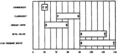
FIG. 1 Comparison of lamps, in terms of lumens per watt
2.2 Compact Fluorescent Lamps (CFL)
The compact fluorescent lamp does not differ in its operating principle from the standard fluorescent lamp, yet the CFL has been designed to address some of the fundamental objections to the widespread application of the linear fluorescent tube in many residential, commercial, and industrial applications. The bulky magnetic ballast, flickering of light and the sometimes audible noise generated by the magnetic ballast were some of the reasons for the unpopularity of the fluorescent tube as a general purpose light source.
The CFL overcomes flickering by operating the lamp at the kHz frequency range and gets rid of the need for an external ballast by incorporating an all-electronic ballast into the base of the fluorescent tube. Thus, CFLs are intended and capable of directly replacing the incandescent lamps without any external auxiliary devices.
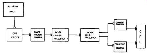
FIG. 2 shows the basic block diagram of a compact fluorescent
lamp.
Note that the electromagnetic interference (EMI) filter and power factor control blocks are necessitated by the presence of electronics for AC/DC conversion DC/AC high frequency conversion circuits inside the package.
2.3 High Intensity Discharge (HID) Lamps
This is a general term for a group of lamps including mercury vapor lamps, metal halide lamps, and high pressure Sodium lamps.
The Mercury Vapor Lamp is a high pressure electric discharge lamp in which the major portion of radiation is produced by excitation of mercury atoms. Switching on the normal mains voltage is not sufficient to start the discharge between the main electrodes. It can, however, start over the very short distance between the main and auxiliary electrodes, the auxiliary electrode being connected to the lamp terminal through a high resistor for limiting the current.
FIG. 2 Block diagram of a CFL
The initial discharge is in the small amount of argon present. The discharge now spreads rapidly until it takes place between the main electrodes. The argon discharge warms up the tube and vaporizes the mercury. The discharge then takes place in the mercury vapor and the argon has negligible effect. The efficacy of the lamp is about 60 lux/watt.
The Metal Halide Lamp is an electric discharge lamp in which the light is produced by the radiation from an excited mixture of metallic vapors (mercury and products of the disassociation of halides). Their construction is similar to high pressure mercury lamps, a number of iodides are added to fill the gaps in the light spectrum, improving the color characteristic of the light. Their efficacy is also higher (up to 80 lux/watt). The sodium Lamp contains neon in addition to the metallic sodium at low pressure. Heat is produced by an initial neon discharge. This causes the sodium to discharge giving a sodium-yellow color. The color is caused by the excitation of sodium vapor. It takes about ten minutes for full light to be reached. A development of this is the high pressure sodium lamp which at high pressure has a widened spectrum to give an adequate cover of all colors, sodium vapor lamps have a very high efficacy of up to 150 lux/watt.
Fluorescent Lamps are popular because they provide longer lifetimes than incandescent, and consume less energy. Further, their low intensity even illumination is preferred in almost all indoor conditions. The high intensity discharge lamps are used primarily in outdoor conditions to light large areas such as streets, parking lots, etc.
3 Introduction to Ballasts
Fluorescent lamp ballasts are devices installed in fluorescent lamp fixtures in order to regulate the voltage and current provided to the lamps. The functions of a ballast in a fluorescent lamp circuit are two fold. First, it must provide a suitable striking (ignition) voltage across the bulb at starting such that an electric arc can sustain between the electrodes afterwards. Secondly, the ballast is responsible for limiting the current flow across the lamp during the normal operation of it. These two requirements of a ballast can be explained from a typical impedance-time characteristics curve of a gas discharge lamp shown in Fig. 3.
As the initial impedance is high, the striking voltage required to ignite the arc would also be higher than the normal operating voltage of a fluorescent lamp.
Immediately after the lamp is struck, the impedance drops to its minimum value, representing a negative resistance characteristics that need some form of current limiting to prevent lamp destruction from excessive current.
While the early magnetic (inductor type) ballasts fulfilled the two necessary requirements of a ballast, the modern electronic ballasts can perform many other functions such as resonant operation, protection from lamp shutdown, failure or removal, and dimming operation, etc. These and other such techniques will be discussed in detail in forthcoming sections.
It should also be noted that while a fluorescent lamp by itself is purely a resistive load, the incorporation of a ballast (either magnetic or electronic type) with it can give rise to potentially objectionable conditions such as low power factor, high order harmonics, and electromagnetic interference. As we will see later in this section, many IC manufacturers have come up with advanced products that solve these problems quite satisfactorily.
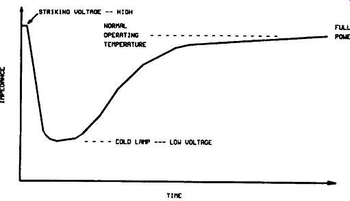
FIG. 3 Impedance-time characteristics of a discharge
lamp
4 Some Definitions and Evaluation of Performance
The primary measure of effectiveness of an electric lamp is its total luminous flux output for a watt of input power. For the purpose of comparison of performance between different light sources, firm definitions of the terms involved are necessary.
4.1 Luminous Flux
The total quantity of visually evaluated radiation (i.e., light) emitted per second by a light source is termed luminous flux and is measured in lumens. The term "visually evaluated radiation" refers to the fact that humans are capable of seeing only a part of the spectrum of electromagnetic radiation.
Moreover, the sensitivity of the human eye differs widely at different wavelengths within this band of frequencies. The luminous flux as measured in lumens takes both these factors into account and, thus, there is no direct correspondence between radiation energy emitted per second of a light source and its lumens output.
4.2 Luminous Efficacy
The luminous flux output of an electric lamp for a watt of input power is defined as the luminous efficacy of a lamp. It’s usually expressed in lumen/watt:
Luminous Efficacy = Luminous Flux / Power Input
Luminous efficacy is sometimes also referred to as lumens-per-watt or lpw rating of a lamp. According to current standards, the luminous efficacy of a fluorescent lamp must be measured inclusive of the power consumption of the ballast.
4.3 Current Crest Factor
The Current Crest Factor is the ratio of the peak lamp current to the rms current.
Current Crest Factor = Peak Current / RMS Current
It’s a consideration of the lamp current wave form. The maximum crest factor recommended by lamp manufacturers so as not to degrade lamp life is around 1.7.
4.4 Ballast Factor
The Ballast Factor is the ratio of the light output of the lamp with the ballast under test to the lamp light output with the ANSI (American National Standards Institution) reference ballast.
Ballast Factor = Lamp light output with test ballast / Lamp light output with reference ballast
4.5 Ballast Efficacy Factor (BEF)
The BEF is the ratio of the ballast factor to the input power of a lamp-ballast system. The BEF is application specific and cannot be used to compare different applications.
Ballast Efficacy Factor = Ballast Factor / Input Power
4.6 Total Harmonic Distortion (THD)
The THD measures the quality of the current waveform produced by a ballast.
The current drawn by a ballast in most cases has a nonsinusoidal waveform and thus can be considered as a series of high order harmonics (i.e., waveforms with frequencies that are multiples of input line frequency) superimposed on the fundamental current waveform. The extent of the presence of such harmonics are measured by THD as defined below.
i_ THD-(h/+ h,'+ h,'+ ...... )2 h,
where each term h i refers to the rms value of the i th harmonic in the current waveform, and hi refers to the rms value of the fundamental component.
5 Conventional Ballasts
In the conventional ballast circuit shown in Fig. 4, the high voltage kick needed to strike the lamp is obtained form the inductor and a bi-metallic switch that also supplies filament current when the contacts are closed. The heated filaments emit space charges that lower the ionization voltage of the mercury vapor within the lamp for easy starting (Mortimer 1994). As the length of the arc tube increases, ionization voltages also increase, requiting ballast to provide stepped up operations voltages as well as higher striking voltages. As a consequence, conventional two and four feet fluorescent lamp ballasts use bulky step up high reactance transformers with output windings to drive two or more lamps.
This magnetic type of ballast is based on a coil of wire surrounding an iron core. Such magnetic ballasts of traditional design are also known as "core and coil ballasts." While a standard magnetic ballast dissipates about 20 percent of the total power, a more efficient magnetic ballast will limit this loss to 12 percent or less. The magnetic ballast is responsible for some harmonic generation due to the non-linear magnetization characteristic of iron.
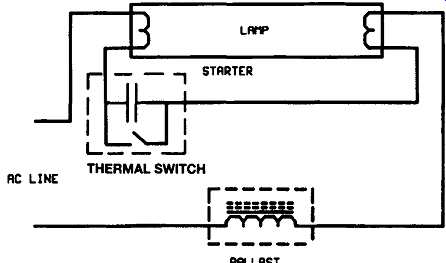
FIG. 4 Basic arrangement of a conventional ballast
The inductance of the magnetic ballast presents poor power factor, typically around 0.5, which needs to be compensated for. Power factor compensation can be done by the use of a capacitor. Even after compensation, low quality magnetic ballasts will have a power factor of around 0.9 due to the relatively high THD of 20-30 percent. The conventional line frequency magnetic ballasts are associated with the following drawbacks.
(i) Flicker from 50/60 Hz power mains, (ii) Significant size and weight, (iii) Low power factor, non-sinusoidal current wave forms, and (iv) Difficulty for dimming.
6 High Frequency Resonant Ballasts
Electronic high frequency resonant ballasts are being increasingly used to drive fluorescent lamps due to their improved energy efficiency, longer lamp life, dimming capabilities, lighter weight, and ability to eliminate flicker.
One of the earliest examples of the electronic operation of fluorescent lamps is found in a 1954 design manufactured by Delco for use in buses. This early electronic ballast was designed to operate six lamps at a total output power of around 140 watts. It operated at around 3000 hertz and was quite large (of the order of 1500 cubic inches). Improvements in semiconductor devices allowed the first practical high frequency ballast to be produced by Triad-Utrad in 1967. These ballasts were simple current fed self oscillating inverters and were also designed for DC input applications.
Electronic ballast circuits have recently undergone a revolution in sophistication from the early bipolar designs of ten years ago. Partly, this has been brought about by the advent of power MOSFET switches with their inherent advantages in efficiency. Most electronic ballasts use two power switches in totem pole (half- bridge) topology and the tube circuits consist of L-C series resonant circuits with the lamp(s) across one of the reactors. Fig. 5 shows the basic topology.
The switches in the circuit of Fig. 5 are power MOSFETs driven to conduct alternatively by two secondary windings on a current transformer. The primary of this transformer is driven by the current in the lamp circuit operating at the resonant frequency of L and C. The circuit is not self starting and must be pulsed started by a Diac connected to the gate of the lower MOSFET.
After the lower switch is turned on, oscillation is sustained and a high frequency square wave (30-80 KHz) excites the L-C resonant current. The sinusoidal voltage across C is magnified by the quality factor (Q) at resonance and develops sufficient amplitude to strike the lamp, which then provides flicker-free illumination.
This circuit has been the standard electronic ballast for many years despite the following inherent shortcomings:
(i) Not self starting, (ii) Poor switching time leading to higher power losses.
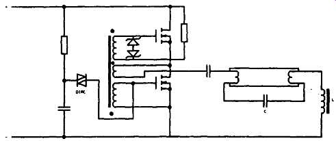
FIG. 5 Electronic ballast using transformer drive
(iii) Labor intensive to manufacture (due to torroidal current transformer, etc.) (iv) Not amenable to dimming, and (v) Expensive to manufacture.
7 The Next Generation of Ballasts
The limitations of the basic electronic ballast circuit design and the need for more efficient lighting systems, coupled with the availability of power MOSFET switches, have created a push for small, efficient, low weight driver ICs. For example International Rectifier's IR2155 self oscillating power MOSFET/insulated gate bipolar transistor (IGBT) gate driver, is one of the first in a family of power ICs, tailored to electronic ballasts for fluorescent lighting, partly because of its small size and low cost (around $2 per 80 units and $1 per 50,000 units). These power ICs can drive low and high side MOSFETs or IGBTs from logic level ground referenced inputs. They provide offset voltage capabilities up to 600 volts DC and, unlike driver transformers, can provide super-clean wave forms of any duty cycle (0-99%). A functional block diagram of the IR 2155 is indicated in Fig. 6. These drivers have two alternative outputs, so that a half bridge or totem-pole configuration of MOSFETs can produce a square wave output. A very useful feature of self oscillating drives is their capability to synchronize the oscillator to the natural resonance of an L-C fluorescent lamp circuit. Fig. 7 shows the concept of an electronic ballast using an IR2155 driver.
The IR2155 provides the designer with self oscillating or synchronized oscillating function, merely with the addition of R T and C T components. The IR2155 MOS gate driver also has internal circuitry which provides a nominal 1 microsecond dead time between outputs and alternating high side and low side outputs for driving half bridge power switches. When used in self oscillating mode, the frequency of oscillation is given by:
1 Fosc -- ~ 1.4RTC T
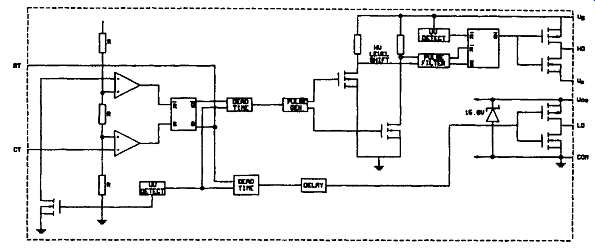
FIG. 6 Functional block diagram of IR 2155 (International
Rectifier, USA )
Note the synchronizing capabilities of the IR2155 driver. The two back to back diodes in series with the lamp circuit are effectively a zero crossing detector for the lamp current. Before the lamp strikes, the resonant circuit consists of L, C 1, and C2 all in series. C2 has a lower value than C 1 so it operates at a higher AC voltage than C2, and in fact, it’s this voltage that strikes the lamp.
After the lamp strikes, C2 is effectively shorted by the lamp voltage drop, and the frequency of the resonant circuit is governed by L and C 1. This causes a shift to a lower resonant frequency during normal operation, again synchronized by sensing the zero crossing of the AC current and using the resonant voltage to control the IR2155 oscillator. A practical ballast circuit using the IR2155 integrated circuit, which is capable of driving two 4 foot tubes, is indicated in Fig. 8.
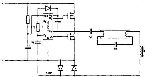
FIG. 7 Electronic ballast using IR2155 driver (International
Rectifier, USA)
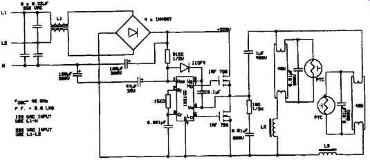
FIG. 8 "Double 40" ballast using the IR 2155
oscillator/driver (International Rectifier, USA)
One of the drawbacks of this circuit is the low power factor and high harmonic current. The circuit in Fig. 7 accepts 115 volts or 230 volts AC 50/60 Hz input to produce a nominal DC bus voltage of 320 volts DC. Since the input of the rectifiers conduct only near the peaks of the AC input voltage, the input power factor is approximately 0.6 lagging with a non-sinusoidal current wave form.
8 Power Factor Correction and Dimming Ballasts
For electronic ballasts, it’s possible to provide power factors exceeding 0.95 by using a boost topology operating at a fixed 50 percent duty cycle. Using the IR2155 driver, it’s also possible to provide dimming merely by changing the duty cycle and hence the boost rates (Wood (April) 1994), as illustrated in Figs9 and 8-10, respectively. Power factor correction is discussed in more detail in the next section.
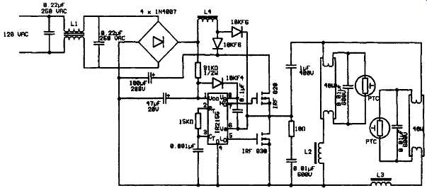
FIG. 9 Ballast with active power factor correction
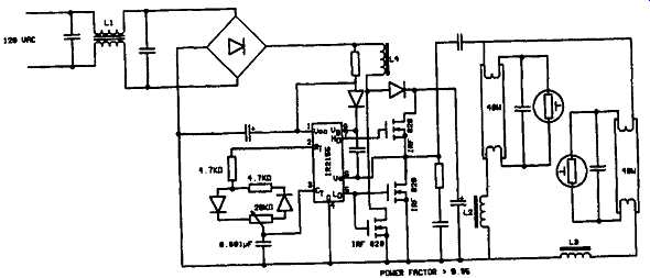
FIG. 10 Dimming ballast
9 Comparison of Compact Fluorescent Lamps Using Magnetic and Electronic Ballasts
The electronic ballast has many advantages over magnetic ballast. These include flicker elimination, low noise, longer ballast life, and of course, energy savings. The energy saving potential of electronic ballasts more than makes up for the additional cost they initially incur. These energy savings can be seen through lower power consumption, and indirectly, in the temperature of the ballast itself.
Electronic ballasts are not without their problems. The total harmonic current distortion is a real concern for engineers. Electronic ballasts can have a THD which far exceeds those of magnetic type ballasts. High harmonic levels have been linked to problems including capacitor bank failures, overheating of transformer windings, excessive neutral currents, de-rating of transformers, and mis-operation of utility protective relaying. They have also been known to disturb sensitive electronic equipment which requires a clean sinusoidal wave form (Datta 1994). The results of a comparative analysis carried out on a number of samples of compact fluorescent lamps (CFL) both with magnetic and electronic ballasts as well as with integral and separate ballasts are shown in Fig. 11.
A study (Lucas and Wijekoon 1995) has shown that most available low cost CFLs could have a very poor power factor. In particular, it has been shown that CFLs with magnetic ballasts can have power factors as low as 0.4 lagging on account of a highly inductive ballast, but they don’t contribute to a high degree of harmonics. On the other hand, CFLs with electronic control gear have an almost equally poor effective power factor, mainly on account of harmonics caused by their power electronics.
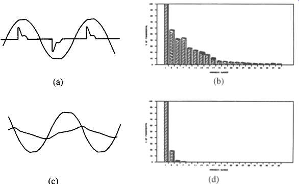
FIG. 11 Comparative Analysis of CFLs (a) Voltage and
current waveforms with an integral electronic ballast (b) Frequency spectrum
for the CFL in Fig. 11(a) (c)
Voltage and current waveforms with an integral magnetic ballast (d) Frequency spectrum in Fig. 11 (c).
10. Future Developments of Electronic Ballasts
Electromagnetic ballasts have demonstrated good reliability due to their relative simplicity. Electronic ballasts, with much higher complexity and relatively fragile active semiconductors, have exhibited failure rates significantly greater than electromagnetic ballasts. As electronic lighting systems become more commonplace, reliability of electronic ballasts become more and more of an issue (Nemer 1994).
The evolution of the electronic ballast from simple inverter to the "smart ballast" of tomorrow, has meant a significant increase in circuit complexity and performance. At the same time, the end user expects a system that provides light on demand every time he or she throws a switch. Compared to many electronic devices, the ballast operates in a hostile environment as defined by ambient temperature. Excessive heat shortens component life.
Quality is essential but does not necessarily equate to reliability. There are important dependent relationships between quality and reliability that include mechanical electrical and economic considerations. Reliability can be improved at three levels. First, the use of high quality components; second, the use of high performance designs, and, third, the use of highly reliable manufacturing techniques.
With the current world energy situation, more and more electromagnetic ballasts will be replaced with electronic lighting. Thus the need for reliable electronic ballasts will keep increasing.
In the same way that electronic ballasts have dramatically increased the efficiency of light production, the next generation of dimming ballasts will provide dramatic energy savings by controlling light more effectively. Dimming electronic ballasts allow strategies, such as daylighting and compensation for lamp depreciation.
Dimming ballasts are available today, but most utilize low voltage control wiring where the cost of installing the control wiring is prohibitive. Integrated wireless control and dimming capabilities will be the basis of the next generation of "intelligent ballasts." Also modern IC manufacturing techniques have made it possible to include complete circuitry for power factor correction and dimming control on a single IC. For example, Micro Linear's ML4830 is an IC with low distortion, high efficiency continuous boost power factor correction together with selectable variable frequency dimming and starting.
For further reading on electronic ballasts references Wood (1994) to Hagar (1993) are recommended.