AMAZON multi-meters discounts AMAZON oscilloscope discounts
- Introduction
- Building Blocks of a Typical High Frequency Off-the-Line Switching Power Supply
- Magnetic Components
- Output Section
- Ancillary, Supervisory and Peripheral Circuits
- Power Supplies for Computers
- Modular SMPS Units for Various Industrial Systems
- Future Trends in SMPS
- Field Trouble-Shooting of Computer Systems Power Supplies
- References
1. Introduction
The basic theory of the switching power supply has been known since the 1930s. Practical switchmode power supplies (SMPS) have existed since the 60s, starting with components designed for other uses and thus poorly characterized for SMPS use. Early SMPS systems were running at very low frequencies, usually between a few KHz to about 20 KHz. Early SMPS designs justified the SMPS techniques for higher output power ratings, usually above 500 watts.
Towards the mid 80s most SMPS units were available for much lower power ratings with multiple output rails, while oscillator frequencies were reaching the upper limit of 100 KHz. Today most switchers operate well above 500 KHz and newer techniques allow the systems to run at several MHz, making use of new magnetics, surface mount components, and the resonant conversion techniques.
The rapid advancement of microelectronics in the last two decades (1975 to 1995) has created a necessity for the development of sophisticated, efficient, light weight power supplies which have a high power-to-volume (W/in^3) ratio with no compromise in performance. The high-frequency switching power supply meets these demands.
Recently it has become the prime powering source in the majority of modem electronic systems. The trends associated with the switchmode power supplies for the electronic products and systems are (a) to reach direct off-the-line design approach, (b) higher frequencies be utilized, (c) output rating/volume being increased and minimizing the components and increasing reliability.
This section discusses the basic blocks of direct off line SMPS units and the newer trends in technology such as distributed DC power, etc. Configurations used for switching blocks are not discussed here as they are covered in the previous chap ter. Introduction to magnetic components, use of magnetic amplifiers, and the mod em trends in high frequency capacitors, etc. are also introduced.
2 Building Blocks of a Typical High Frequency Off-the-Line Switching Power Supply
The building blocks of a typical high-frequency off-the-line switching power supply are depicted in Fgr. 1(a). The basic operation of the switching power supply was described in the previous section. This block diagram shows other important sections such as the AC line RFI filter block, the ancillary and supervisory blocks, and the I/O isolation block. The EMI/RFI filter could be either part of the power supply or external to it, and is generally designed to comply to national or international specifications, such as the FCC class A or class B and VDE-0871.
Within the past few years, due to emphasis placed on the power quality issues, power factor correction as applicable to the nonlinear behavior of the input current waveform of a switcher has become an important issue. For power supplies with output capacity over 700VA power factor correction is becoming compulsory and Section 9 provides details related to power factor correction techniques. Fgr. 1 (b) shows a block diagram of a SMPS with power factor correction.
The ancillary and supervisory circuits are used to protect the power supply as well as the load from fault conditions. Generally, each power supply has current limit protection to prevent its destruction during overload conditions. Overvoltage protection is part of the supervisory circuits used to protect the load from power supply failures. It’s important to note that although in a linear power supply, over voltage conditions were common during the short circuits of the series-element, in a switching power supply, failure of the switching element normally results in a non-output condition. However, the output of the switcher will go high if the feed back loop is opened.
Input/output isolation is essential to an off-the-line switcher. The isolation may be optical or magnetic, and it should be designed to comply to Underwriters Laboratories (UL), Canadian Standards Association (CSA), Verband Deutscher Electronotechniker (VDE), or International Electrotechnical Commission (IEC) safety standards. Thus the UL and CSA require 1000 V AC isolation voltage with stand while VDE and IEC require 3750V AC. Consequently, the power transformer has to be designed to the same safety isolation requirements also.
2.1 The Input Section
As mentioned previously, an off-the-line switching power supply rectifies the AC line directly without requiring a low-frequency line isolation transformer between the AC mains and the rectifiers. Since in most of today's electronic equipment the manufacturers are generally addressing an international market, the power supply designer must use an input circuit capable of accepting many different line voltages, normally 90 to 130V AC or 180 to 260V AC. Fgr. 2 shows a realization of such a circuit by using the voltage doubler technique. When the switch is closed, the circuit may be operated at a nominal line of 110V AC.
During the positive half cycle of the AC, capacitor C1 is charged to the corresponding peak voltage, approximately 155V DC, through diode D1. During the negative half cycle, capacitor C2 is charged to 155V DC through diode D 4. Thus, the resulting DC output will be the sum of the voltages across C1 + C 2 , or 310 V DC.
When the switch is open, D1 to D4 form a full-bridge rectifier capable of rectifying a nominal 220-V AC line and producing the same 310V DC output voltage.
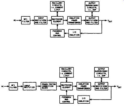
FGR. 1 The building blocks of a typical off-the-line high-frequency switching
power supply (a) Without power factor correction (b) Withpower factor
correction
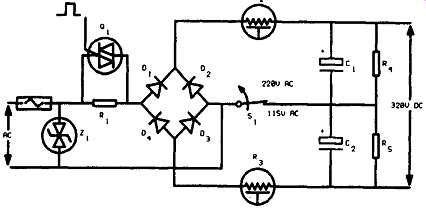
FGR. 2 Input section of an SMPS showing basic components.
2.1.1 Selection of Basic Components
In selecting the primary components such as the bridge rectifier (or the diodes) and the filter capacitors, the designer must look for several important specifications.
2.1.2 Diodes and Capacitors
For diodes, maximum forward rectification current capability, Peak Inverse Voltage (PIV) capability, and the surge current capability (to withstand the peak cur rent associated with turn-on) are the most important specifications.
Proper calculation and selection of the input rectifier filter capacitors is very important, since this will influence the performance parameters such as low frequency AC tipple at the output power supply and the holdover time. Normally high-grade electrolytic capacitors with high ripple current capacity and low Equivalent Series Resistance (ESR) are used with a working voltage of 200 V DC minimum. Resistors R 4 and R 5, shown in Fgr. 2 shunting the capacitors, pro vide a discharge path when the supply is switched off.
2.1.3 Fuses
Modem fuse technology is an advanced science. New and better fuses are continually being developed to meet the more demanding requirements for protection of semiconductor circuitry. To obtain the most reliable long-term performance and best protection, a fuse must be knowledgeably chosen to suit the application.
Fuses are categorized by three major parameters; current rating, voltage rating, and, most important, "let-through" current, or I2t rating.
2.1.4 Current and Voltage Rating
Current rating of a fuse is the rms value or the maximum DC value that must exceed before blowing the current demanded by the protected circuit. The voltage rating of a fuse is not necessarily linked to the supply voltage. Rather, the fuse volt age rating is an indication of the fuse's ability to extinguish the arc that is generated as the fuse element melts under fault conditions.
The voltage across the fuse element under these conditions depends on the supply voltage and the type of circuit. For example, a fuse in series with an inductive circuit may see voltages several times greater than the supply voltage during the clearance transient.
2.1.5 "Let-Through" Current (12t Rating)
This characteristic of a fuse is defined by the amount of energy that must be dissipated in the fuse element to cause it to melt. This is sometimes referred to as the pre-arcing let-through current. To melt the fuse element, heat energy must be dissipated in the element more rapidly than it can be conducted away. This requires a defined current and time product.
The heat energy dissipated in the fuse element is in the form of watt-seconds (joules), or I2.Rt for a particular fuse. Since the fuse resistance is a constant, this is proportional to I2t, normally referred to as the I2t rating for a particular fuse or the pre-arcing energy. The I2t rating categorizes fuses into the more familiar "slow blow, .... normal," and "fast-blow" types. It should be noted that the I2t energy can be as much as two decades greater in a slow-blow fuse of the same DC current rating. For example, a 10A fuse can have an I2t rating ranging from 5 A2.s for a fast fuse to 3000 A2.s for a slow fuse. Selection of fuse ratings for off line SMPS are discussed in Billings.
For high power semiconductors manufacturers indicate a value of I2t, for 10 ms (for 50Hz) or 8.3 ms (for 60 Hz), that should not be exceeded. Comparing this value with the fuse I2t permits us to verify the protection. De Palama and Deshayes (1996) provide details of protecting power semiconductors using the appropriate fuses.
2.2 Input Protective Devices
2.2.1 Inrush Current
An off-the-line switching power supply may develop extremely high peak inrush currents during turn-on, unless the designer incorporates some form of current limiting in the input section. These currents are caused by the charging of the filter capacitors, which at turn-on present a very low impedance to the AC lines, generally only their ESR. If no protection is employed these surge currents may approach hundreds of amperes.
Two methods are widely employed in introducing an impedance to the AC line at turn-on and in limiting the inrush current to a safe value. One is using a resistor-triac arrangement, and the other using negative temperature coefficient (NTC) thermistors.
Fgr. 2 shows how these elements R 2 and R 3 may be employed in a power supply.
2.2.2 The Resistor-Triac Technique
Using this inrush current limiting technique, a resistor is placed in series with the AC line. The resistor is shunted by a triac which shorts the resistor out when the input filter capacitors have been fully charged. This arrangement requires a trigger circuit which will fire the triac on when some predetermined conditions have been met. Care must be taken in choosing and heat-sinking the triac so that it can handle the full input current when it’s turned on.
2.2.3 The Thermistor Technique
This method uses NTC thermistors placed on either the AC lines or the DC buses after the bridge rectifiers, as shown in Fgr. 2. When the power supply is switched on the resistance of the thermistor(s) is essentially the only impedance across the AC line, thus limiting the inrush current.
As the capacitors begin to charge, current starts to flow through the thermistors heating them up. Because of their negative temperature coefficient, as the thermistors heat up their resistance drops. When the thermistors are properly chosen, their resistance at steady-state load current will be a minimum, thus not affecting the overall efficiency of the power supply.
2.2.4 Input Transient Voltage Protection
Although the AC mains are nominally between 110V to 240V AC, it’s common for high-voltage spikes to be caused by nearby inductive switching or natural causes such as electrical storms or lightning. On the other hand, inductive switching voltage spikes may have an energy content:
W = 1/2 x L I^2
Where L is the leakage inductance of the inductor, and I is the current flowing through the winding. Therefore, although these voltage spikes may be short in duration, they may carry enough energy to prove fatal for the input rectifiers and the switching transistors, unless they are successfully suppressed.
The most common suppression device used in this situation is the metal oxide varistor (MOV) type transient voltage suppresser, and it may be used as shown in Fgr. 2 across the AC line input. This device acts as a variable impedance; that is, when a voltage transient appears across the varistor, its impedance sharply decreases to a low value, clamping the input voltage to a safe level. The energy in the transient is dissipated in the varistor. In more modem designs solid state devices and MOVS are mixed to form more guaranteed protection. Section 6 provides details.
2.3 RFI/EMI Filter
Every switching power supply is a source of Radio Frequency Interference (RFI) generation because of the very fast rise and fall times of the current and voltage waveforms inherent in the DC-DC converter operation. The main sources of switching noise are the switching transistor(s), the mains rectifier, the output diodes, the protective diode for the transistor, and of course the control unit itself. Depending upon the topology of the converter used, the RFI noise level at the mains input may vary.
Flyback converters, which by design have a triangular input current wave form, generate less conducted RFI noise than converters with rectangular input cur rent waveforms, such as forward or bridge converters. Fourier analysis shows that the amplitudes of the high-frequency harmonics of a triangular current waveform drop at a rate of 40 decibels per decade, compared to a 20 decibel per decade drop for a comparable rectangular current waveform.
United States and international standards for EMI-RFI have been established which require the manufacturers of electronic equipment to minimize the radiated and conducted interference of their equipment to acceptable levels. In the United States the guiding document is the Federal Communications Commission (FCC) Docket 20780, while internationally the West German Verband Deutscher Elektronotechniker (VDE) safety standards have been widely accepted. It’s very important to understand that both the FCC and VDE standards exclude subassemblies from compliance to the rule; rather, the final equipment, where the switching power supply is used, must comply with the EMI-RFI specifications.
Both the FCC and VDE are concerned with the suppression of RFI generated by equipment connected to the AC mains employing high-frequency digital circuitry. The VDE has subdivided its RFI regulations into two categories, the first being unintentional high-frequency generation by equipment with rated frequencies from 0-10 kHz, i.e., VDE-0875 and VDE-0879, and the second dealing with intentional high-frequency generation by equipment using frequencies above 10 kHz, i.e., VDE-0871 and VDE-0872. The FCC on the other hand includes in its RFI regulations all electronic devices and systems which generate and use timing signals or pulses at a rate greater than 10 kHz. Chryssis (1989) summarizes the FCC and VDE RFI requirements.
Fgr. 3 shows a differential noise filter and a common-mode noise filter in series. In many cases the common-mode filter is used alone, as it can often eliminate as much as 90 percent of the unwanted noise.
In EMI/RFI filters, the cores used for the common mode filter are mainly high permeability toroids. Here, the cores are wound either bifilar, using both of the line current wires, or two identical windings on opposing sides of a toroid. In this way the flux created by each line current cancels the flux from the other line so the high line current does not saturate the core.
Because of this arrangement, any unwanted noise that attempts to flow out of the power supply through both input leads in the same phase and same direction will be attenuated by the high impedance of the core. Ferrite toroids with permeabilities of 5,000 (J Material), 10,000 (W material), and 15,000 (H material) are popular because of their high permeability or impedance characteristics.
In-line filters are necessary to eliminate noises that are in phase with the line currents. Heavy line currents flowing through the windings of these filters tend to saturate the core. Therefore, the cores must be gapped; preferred types are ferrites and powder cores.
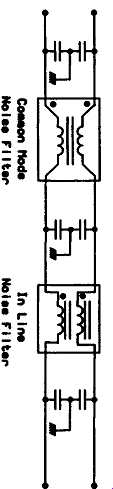
FGR. 3 EMI/RFI filter ---
Commode In Line
Noise Filter
In the RFI/EMI filter blocks the capacitors bypass the high frequency components generated from the switching block due to low effective impedance at the high frequencies. Magnetics Inc. (1995) provides design details of RFI/EMI filters.
3 Magnetic Components
3.1 Transformers and Inductors
Magnetic elements are the cornerstone of all switching power supply designs but are also the least understood. There are three types of magnetic components inside switching power supplies: a forward-mode transformer or a flyback-mode transformer, an AC filter inductor, and a DC filter inductor or a magnetic amplifier, etc.
Each has its own design approach. Although the design of each of these magnetic components can be approached in an organized step-by-step fashion, it’s beyond the intent of this section. For further information Brown is suggested.
3.1.1 Magnetic Materials
Magnetic materials can be divided into three broad categories, each with its own distinct range of characteristics and capabilities:
i. Magnetic metals and alloys, in tape or laminated form (e.g., silicon steel, Mumetal, Permalloy, Amorphous metals);
ii. Powdered magnetic metals (e.g., "Powdered Iron," Moly Permalloy Power); and iii. Magnetic ceramics, or ferrites.
3.1.1.1 Magnetic Metals
Typically these have a high saturation flux density (7 to 23KG) and a high permeability (1K to 200K). Electrical conductivity is also high, requiting their use in laminated or tape form to reduce eddy current loss. A large range of shapes is available, limited primarily to "two dimensional" shapes by the wound tape or laminated construction.
The high flux capability makes them most suitable as line frequency (50 to 400 Hz) transformers and inductors. Eddy current losses limit use at high frequency, although some find application up to several hundred KHz.
3.1.1.2 Powdered Metals
These are magnetic metals which are powdered, coated with an insulator, and pressed and sintered to shape. Eddy currents are reduced by the small particle size, extending the useful frequency range to a few megahertz in some applications.
The insulated particles create a distributed air gap, giving these materials a low permeability, typically in the range of 8 to 80, with values to 550 obtainable in MPP.
The low permeability and a tolerance for DC current makes these materials suitable for filter inductors at medium frequencies (typically 1 to 100 KHz).A relatively stable and well defined permeability allows them to be used for nonadjustable tuning inductors, with a typical tolerance of a few percent. Saturation flux densities are typically in the range of 5 to 10 KG, but a very gradual saturation characteristic limits the maximum flux when inductance variations must be minimized.
Available core shapes tend to be limited; toroids are the most common, with "E" cores, pot and cup cores, and a few similar shapes also available in some materials.
3.1.1.3 Ferrites
Ferrites are dark grey or black ceramic materials. They are very hard, brittle, and chemically inert. Most common ferrite materials such as MnZn and NiZn exhibit good magnetic properties below Curie Temperature (T_c). Ferrites are characterized by very high resistivities, making them the most suitable material for transformers and inductors operating at high frequencies (up to tens of MHZ) when low loss or high Q is of major concern. Saturation flux densities are low, in the 2 to 5 KG range, with permeabilities in the middle range of a few hundred to 15,000.
Ferrites have the widest range of available core shapes, including any of the shapes for the other materials. Maximum linear dimensions are limited to a few inches by standard fabrication processes, although large cores can be assembled in sections.
The flexibility in shape often makes ferrites the material of choice, even when their other desirable properties are not required. They can easily be magnetized and have a rather high intrinsic resistivity. These materials can be used up to very high frequencies without laminating as is the normal requirement for magnetic metals.
NiZn ferrites have a very high resistivity and are therefore most suitable for frequencies over 1 MHz but MnZn ferrites exhibit higher permeabilities (u_i) and saturation induction levels (Bs). Different kinds of power ferrite material are avail able from many vendors. For example available power ferrites from Phillips are available as per data in Table 4.
Fgr. 4 indicates the typical block diagram of a SMPS with magnetic components. Table 1 indicates the core types and magnetic materials usable in each block.
A comparison of the characteristics of core material, advantages, and disadvantages are described in Magnetics Inc.
===
TABLE 1
USA) Usable Magnetic Materials in SMPS Blocks (Magnetics Inc., Core Material and Type Common Mode Filter In-line Filter PFC Inductor Output Transformer Magnetic Amplifier Filter Inductor Ferrite toroids Ferrite shapes (ungapped) "Ferrite pot cores Ferrite shapes (gapped) MPP 50Ni-50Fe powder cores Gapped ferrites Powdered iron SiFe laminations Kool M~ Powder cores Ultra Mix Amorphous tape cores Ni-Fe tape wound cores Amorphous tape wound cores Cut core Ni-Fe/~Ni-Fe laminations Cobalt-base amorphous tape wound cores Square loop ferrite toroids
===
===
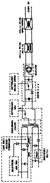
FGR. 4 Typical SMPS blocks indicating the use of magnetic components
Table 2 compares the core materials.
3.1.2 Core Geometry and Common Core Materials
Cores come in many shapes and sizes. The most common core types are shown in Fgr. 5. There are many more types, but they are all based upon these basic styles. Some of the important considerations when selecting a core type are core material, cost, the output power of the power supply, the physical volume the transformer or inductor must fit within, and the amount of RFI shielding the core must provide. Table 3 provides ferrite core geometry considerations.
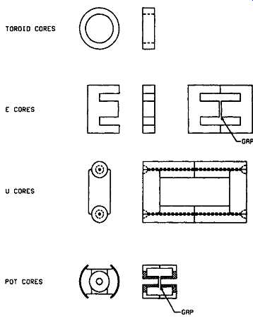
FGR. 5 Common core types
TABLE 2 Core Material Considerations (Magnetics, Inc., USA) Pot Core------Flux Density Initial Perm.
Frequency* Range ..
TABLE 4 -;3 Ferrite Core Geometry Considerations
Core Cost
Slab-sided Core ,
Core Toroid PQ Core
Bobbin Cost
high,. low
Winding Cost
Low; medium very low high low medium none high low high low
===
For modem switching power supplies some of the commonly used core materials are F, K, N, R, and P materials from Magnetics Inc.; 3C8, 3C85 from FerroxCube Inc; or H7C4 and H7C40 materials from TDK. These ferrite materials offer the low core losses at the operating frequencies between 80KHz to 2.0 MHz.
Table 4 indicates the available power ferrite materials from Philips, their usage, and characteristics.
Resonant power supplies make it possible to exploit the area beyond 1 MHz, which requires power ferrite transformers with useful properties in the 1-3 MHz frequency range. Meeting this need is a new power transformer core material, 3F4, MnZn ferrite. Precise control of the fine-grained microstructure, which requires both a high purity powder processing and an adapted sintering technology, enables the 3F4 material to obtain these properties. The chemical composition includes dopants to reduce the hysteresis loss and high frequency wall damping loss. The material also suppresses electrical conductivity and thus the eddy current losses.
TABLE 4 Power Ferrite Materials from Philips, Their Usage and Frequency Characteristics
Material Grade; Characteristics Usage; Available core types
3.1.3 Winding Techniques and Practical Considerations
The design and the winding technique used in the magnetic component's design has a great bearing on the reliability of the overall power supply. Two situations arise from a poor transformer design; high voltage spikes are generated by the rate of transitions in current within the switching supply, and the possibility of core saturation can arise during an abnormal operational mode.
Voltage spikes are caused by a physically "loose" winding construction of a transformer. The power supply depends upon the quick transmission of transitions in current and voltage between the transformer windings. When the windings are physically wound distant from one another, the leakage inductances store and release a portion of the energy supplied to a winding in the form of voltage spikes.
It also delays the other windings from seeing the transition in the drive winding.
Spikes can cause the semiconductors to enter avalanche breakdown and the part can instantly fail if enough energy is applied. It can also cause significant RFI problems.
A snubber is usually the solution, but this lowers the efficiency of the power supply. Core saturation occurs when there are too few turns on a transformer or inductor. This causes the flux density to be too high and at high input voltages or long pulse widths, the core can enter saturation. Saturation is when the core's cross sectional area can no longer support additional lines of flux. This causes the permeability of the core to drop, and the inductance value to drop drastically.
3.1.4 Transformers
For forward mode operation transformers may use either tape wound cores or ferrite cores. Tape wound cores are used at the lower frequencies because their high flux density minimizes the transformer size. As the frequency increases, high frequency materials are required and the tape thickness must be reduced, both of which increase the core cost. This makes the tape wound core more costly than ferrites at frequencies over 10 KHz.
Tape wound cores often have to be gapped with a minimal type air gap. Figure 4~ shows the hysteresis loop of a typical tape wound core both with and without an air gap. Because the loop is extremely square, any unbalance in the switching process could cause saturation for some part of the cycle, thus generating extra losses in the circuit and distorting the output. As indicated in Fgr. 6(a), the gapped core will require a large difference in transistor currents before it will saturate the core.
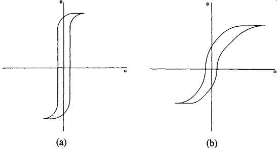
FGR. 6 B-H loop for a tape wound core (a) Ungapped (b) Gapped
One other method to eliminate this problem of core saturation is to use a composite core. These cores are made with an ungapped tape wound core surrounded by another tape wound core containing a small air gap. Composite cores avoid the problems of unbalanced transistors and also reduce or eliminate spikes in the output. The state of the art power supplies running at frequencies over 200 KHz, where the losses could be high, ferrites are the dominant core material because of their lower cost and availability of variety of shapes and sizes.
3.1.5 Flyback Transformers
The transformer cores for flyback circuits require an air gap in the core so that they don’t saturate from the DC current flowing in their windings. As mentioned above, the tape wound core and ferrite core can both be provided with air gaps. The toroidal Permalloy powder core is also used because it offers a distributed, type air gap. The frequency of the unit will dictate the selection of either tape wound cores or ferrites as described previously, while the powder cores will operate at frequencies up to 50 KHz. Operation of the flyback converter is based on the storage of energy in the core and its air gap during the on time of the switch and discharging the energy into the load during the switch's off time. The magnetic core operates in one quadrant of its B-H curve. For high energy transfer in a small volume, the core should have the B-H curve shown in Fgr. 7. An ideal core has a large available flux swing (AB), low core losses, relatively low effective permeability, and low cost.
Moly Permalloy Powder (MPP) cores, gapped ferrites, Kool Mix, and powdered iron cores are used in this application.
In the case of ferrites, to increase their energy transfer ability ferrites must have an air gap added into the core's structure (Fgr. 8). Although the air gap increases the energy transfer of the ferrite core, it can create EMI problems. Better shielded core shapes, such as pot cores, PQ cores, RM cores, and EP cores, are used to combat stray magnetic flux emitted from the air gap. The disadvantage of these shapes is higher cost.
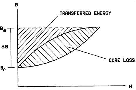
FGR. 7 B-H curve for flyback power supply --- TRRNSFERRED ENERGY; CORE
LOSS
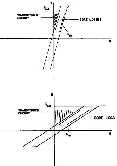
FGR. 8 Effect of gap in ferrite core (a) Ungapped ferrite (b) Gapped ferrite
3.1.6 Inductors
The switching regulator usually includes a power inductor. Because of the large DC current through its windings, the core must have a large air gap to keep it from saturating. Cores used here are gapped ferrite cores, Permalloy powder cores, and high flux powder cores.
In the current wave form, because there is usually only a small ripple, the AC flux swing in the core is small. Therefore, powder iron cores and silicon laminations may also be used. They are less expensive than the above mentioned cores but have much higher losses, and, therefore, care must be taken in the design of such units to avoid overheated inductors and possible damage that may be caused to other components.
Ferrite E cores and pot cores offer the advantages of decreased cost and low core losses at high frequencies. For switching regulators, F or P materials are recommended because of their temperature and DC bias characteristics. By adding air gaps to these ferrite shapes, the cores can be used efficiently while avoiding saturation.
3.2 Planar Magnetics
The concept of planar magnetics has existed for many years, however, the idea has recently gained popularity due to its low profile configurations. The windings consist of either copper spiral turns on single or double-sided printed circuit boards or stamped, flat copper foil windings.
The windings are separated from each other and the core by thin sheets of Kapton or Mylar insulation. When necessary, they are separated by special plastic bobbins to maintain safety specifications. These assemblies are available in a fully encapsulated form to meet certain military specifications.
Advantages of the planar construction include low profile configuration (e.g., high efficiency, lightweight, and uniform construction); high power density (e.g., low manufacturing times, and high frequencies of operation). Some disadvantages include high costs of design and tooling for printed circuit boards and special ferrite cores, inefficient means of terminating windings to the board, and thermal tempera ture rise of magnetics.
Another approach to planar magnetics is the multilayer circuit board, a more condensed configuration. The primary and secondary windings are stacked vertically on different layers of a circuit board with a thin film of FR4 separating them.
The multilayer circuit board offers all the advantages of the planar configuration and provides an even lower profile transformer. An additional advantage of the multilayer build is that heat is transferred out of the transformer more efficiently so that thermal rise is not as much of a problem compared to single or double layer types.
3.2.1 Planar Magnetics and New PWM ICs
With the distributed power architectures (discussed later) being widely adopted by the industry recently, new D/CMOS PWM ICs, combined with integrated PCB transformers, allow simple flyback, and forward converters to operate at frequencies up to 1 MHz, with performance similar to zero switching topologies.
An example of such an IC is Si 9114 from Siliconix Inc..
Planar transformers can be more efficiently used if the subsystem is viewed as an entire unit that includes the power supply and the load. Usually the load is some type of digital circuit and will include a microprocessor and memory, as well as custom designed ASICs. System complexity has so increased that many designers are now using multilayer printed circuit boards where six and even more layers have become common. These systems can now utilize a "free transformer" directly in the PC board as shown in Fgr. 9.
Persson (1994), Magnetics Inc. (1997), Martin (1983), Horgan (1994), and Magnetics Inc. (1995) provide practical details related to magnetic materials and cores used in switchmode power supply systems.
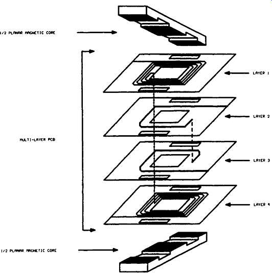
Above: Fig. 9 Integrated PC board planar transformer