AMAZON multi-meters discounts AMAZON oscilloscope discounts
Generation, transmission, and heavy-power utilization of ac electric energy almost invariably involve a type of system or circuit called a polyphase system or polyphase circuit. In such a system, each voltage source consists of a group of voltages having related magnitudes and phase angles. Thus, an n-phase system employs voltage sources which typically consist of n voltages substantially equal in magnitude and successively displaced by a phase angle of 360°/n. A three-phase system employs voltage sources which typically consist of three voltages substantially equal in magnitude and displaced by phase angles of 120 ° . Because it possesses definite economic and operating advantages, the three-phase system is by far the most common, and consequently emphasis is placed on three-phase circuits in this Section.
The three individual voltages of a three-phase source may each be connected to its own independent circuit. We would then have three separate single-phase systems.
Alternatively, as will be shown in Section 1, symmetrical electric connections can be made between the three voltages and the associated circuitry to form a three-phase system. It is the latter alternative that we are concerned with in this Section. Note that the word phase now has two distinct meanings. It may refer to a portion of a polyphase system or circuit, or, as in the familiar steady-state circuit theory, it may be used in reference to the angular displacement between voltage or current phasors. There is very little possibility of confusing the two.
1. GENERATION OF THREE-PHASE VOLTAGES
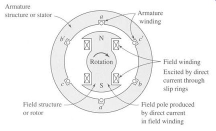
FIG. 1 Elementary two-pole, three-phase generator.
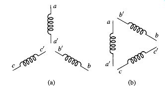
FIG. 2 Schematic representation of the windings of Fig. 1.
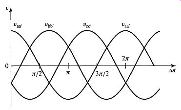
FIG. 3 Voltages generated in the windings of Figs. 1 and 2.
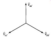
FIG. 4 Phasor diagram of generated voltages.
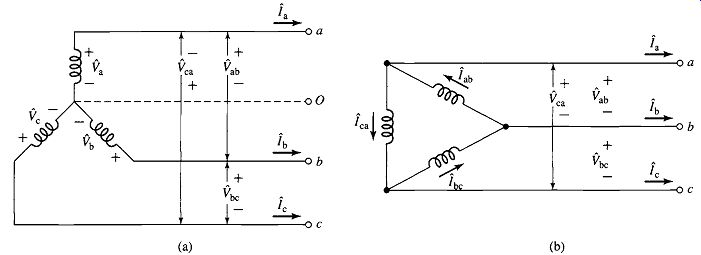
FIG. 5 Three-phase connections" (a) Y connection and (b) A connection.
Consider the elementary two-pole, three-phase generator of Fig. 1. On the armature are three coils aa', bb', and cc' whose axes are displaced 120 ° in space from each other. This winding can be represented schematically as shown in Fig. 2. When the field is excited and rotated, voltages will be generated in the three phases in accordance with Faraday's law. If the field structure is designed so that the flux is distributed sinusoidally over the poles, the flux linking any phase will vary sinusoidally with time, and sinusoidal voltages will be induced in the three phases. As shown in Fig. 3, these three voltages will be displaced 120 ° electrical degrees in time as a result of the phases being displaced 120 ° in space. The corresponding phasor diagram is shown in Fig. 4. In general, the time origin and the reference axis in diagrams such as Figs. .3 and A.4 are chosen on the basis of analytical convenience.
There are two possibilities for the utilization of voltages generated in this manner.
The six terminals a, a', b, b', c, and c' of the three-phase winding may be connected to three independent single-phase systems, or the three phases of the winding may be interconnected and used to supply a three-phase system. The latter procedure is adopted almost universally. The three phases of the winding may be interconnected in two possible ways, as shown in Fig. 5. Terminals a', b', and c t may be joined to form the neutral o, yielding a Y connection, or terminals a and b t, b and c t, and c and a t may be joined individually, yielding a A connection. In the Y connection, a neutral conductor, shown dashed in Fig. 5a, may or may not be brought out. If a neutral conductor exists, the system is a four-wire, three-phase system; if not, it is a three-wire, three-phase system. In the A connection (Fig. 5b), no neutral exists and only a three-wire, three-phase system can be formed.
The three phase voltages of Figs. 3 and 4, are equal and displaced in phase by 120 degrees, a general characteristic of a balanced three-phase system. Furthermore, in a balanced three-phase system the impedance in any one phase is equal to that in either of the other two phases, so that the resulting phase currents are also equal and displaced in phase from each other by 120 degrees. Likewise, equal power and equal reactive power flow in each phase. An unbalanced three-phase system, however, may be unbalanced in one or more of many ways; the source voltages may be unbalanced, either in magnitude or in phase, or the phase impedances may not be equal. Note that only balanced systems are treated in this Section, and none of the methods developed or conclusions reached apply to unbalanced systems. Most practical analyses are conducted under the assumption of a balanced system. Many industrial loads are three-phase loads and therefore inherently balanced, and in supplying single-phase loads from a three-phase source definite efforts are made to keep the three-phase system balanced by assigning approximately equal single-phase loads to each of the three phases.
2. THREE-PHASE VOLTAGES, CURRENTS, AND POWER
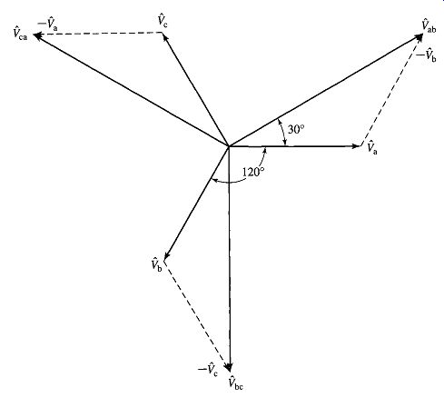
FIG. 6 Voltage phasor diagram for a Y-connected system.
When the three phases of the winding in Fig. 1 are Y-connected, as in Fig. 5a, the phasor diagram of voltages is that of Fig. 6. The phase order or phase sequence in Fig. 6 is abc; that is, the voltage of phase a reaches its maximum 120 ° before that of phase b.
The three-phase voltages Va, ~rb, and f'c are called line-to-neutral voltages.
The three voltages f'ab, f'bc, and f'ca are called line-to-line voltages.
[...]
3. Y- and Δ-CONNECTED CIRCUITS
Three specific examples are given to illustrate the computational details of Y- and Δ-connected circuits. Explanatory remarks which are generally applicable are incorporated into the solutions.
4. ANALYSIS OF BALANCED THREE-PHASE CIRCUITS; SINGLE-LINE DIAGRAMS
By combining the principle of A-Δ equivalence with the technique revealed by Example 1, a simple method of reducing a balanced three-phase-circuit problem to its corresponding single-phase problem can be developed. All the methods of single-phase-circuit analysis thus become available for its solution. The end results of the single-phase analysis are then translated back into three-phase terms to give the final results.
In carrying out this procedure, phasor diagrams need be drawn for only one phase of the Y connection, the diagrams for the other two phases being unnecessary repetition. Furthermore, circuit diagrams can be simplified by drawing only one phase.
Examples of such single-line diagrams are given in Fig. 15, showing two three-phase generators with their associated lines or cables supplying a common substation load. Specific connections of apparatus can be indicated if desired. Thus, Fig. 15b shows that G1 is Y-connected and G2 is Δ-connected. Impedances are given in ohms per phase.
When one is dealing with power, reactive power, and voltamperes, it is sometimes more convenient to deal with the entire three-phase circuit at once instead of concentrating on one phase. This possibility arises because simple expressions for three-phase power, reactive power, and voltamperes can be written in terms of line-to-line voltage and line current regardless of whether the circuit is Y -or Δ-connected.
Thus, from Eqs. 18 and 19, three-phase power is [...]

FIG. 15 Examples of single-line diagrams.
It should be borne in mind, however, that the power-factor angle 0, given by Eq. 24, is the angle between Vp and Ip and not that between V_1-1 and I_p.
5. OTHER POLYPHASE SYSTEMS
Although three-phase systems are by far the most common of all polyphase systems, other numbers of phases are used for specialized purposes. The five-wire, four-phase system (Fig. 16) is sometimes used for low-voltage distribution. It has the advantage that for a phase voltage of 115 V, single-phase voltages of 115 (between a, b, c, or d and o, Fig. 16) and 230 V (between a and c or b and d) are available as well as a system of polyphase voltages. Essentially the same advantages are possessed by four-wire, three-phase systems having a line-to-neutral voltage of 120 V and a line-to-line voltage of 208 V, however.
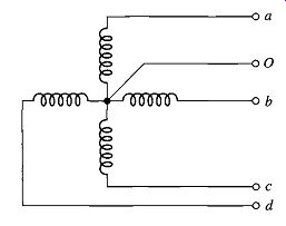
FIG. 16 A five-wire, four-phase system.
Four-phase systems are obtained from three-phase systems by means of special transformer connections. Half of the four-phase system--the part aob (Fig. 16), for example m constitutes a two-phase system. In some rectifier circuits, 6-, 12-, 18-, and 36-phase connections are used for the conversion of alternating to direct current.
These systems are also obtained by transformation from three-phase systems.
When the loads and voltages are balanced, the methods of analysis for three-phase systems can be adapted to any of the other polyphase systems by considering one phase of that polyphase system. Of course, the basic voltage, current, and power relations must be modified to suit the particular polyphase system.