AMAZON multi-meters discounts AMAZON oscilloscope discounts
Both amplitude and waveform of the generated voltage and armature mmf's in machines are determined by the winding arrangements and general machine geometry. These configurations in turn are dictated by economic use of space and materials in the machine and by suitability for the intended service. In this Section we supplement the introductory discussion of these considerations in Section 4 by analytical treatment of ac voltages and mmf's in the balanced steady state. Attention is confined to the time-fundamental component of voltages and the space-fundamental component of mmf's.
1. GENERATED VOLTAGES
In accordance with Eq. 4.50, the rms generated voltage per phase for a concentrated winding having Nph turns per phase is

E = ~/2 ~fNph~ (Eq. 1)
where f is the frequency and • the fundamental flux per pole.
A more complex and practical winding will have coil sides for each phase distributed in several slots per pole. Equation 1 can then be used to compute the voltage distribution of individual coils. To determine the voltage of an entire phase group, the voltages of the component coils must be added as phasors. Such addition of fundamental-frequency voltages is the subject of this article.
1.1 Distributed Fractional-Pitch Windings
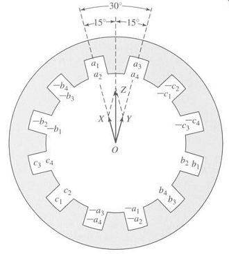
FIG. 1 Distributed two-pole, three-phase full-pitch armature winding
with voltage phasor diagram.
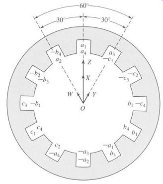
FIG. 2 Distributed two-pole, three-phase fractional-pitch armature
winding with voltage phasor diagram.
A simple example of a distributed winding is illustrated in Fig. 1 for a three-phase, two-pole machine. This case retains all the features of a more general one with any integral number of phases, poles, and slots per pole per phase. At the same time, a double-layer winding is shown. Double-layer windings usually lead to simpler end connections and to a machine which is more economical to manufacture and are found in all machines except some small motors below 10 kW. Generally, one side of a coil, such as a l, is placed in the bottom of a slot, and the other side, -a1, is placed in the top of another slot. Coil sides such as al and a3 or a2 and a4 which are in adjacent slots and associated with the same phase constitute a phase belt. All phase belts are alike when an integral number of slots per pole per phase are used, and for the normal machine the peripheral angle subtended by a phase belt is 60 electrical degrees for a three-phase machine and 90 electrical degrees for a two-phase machine.
Individual coils in Fig. 1 all span a full pole pitch, or 180 electrical degrees; accordingly, the winding is a full-pitch winding. Suppose now that all coil sides in the tops of the slots are shifted one slot counterclockwise, as in Fig. 2. Any coil, such as a1, -a 1, then spans only five-sixths of a pole pitch or 5/6 (180) = 150 electrical degrees, and the winding is a fractional-pitch, or chorded, winding. Similar shifting by two 2 slots yields a 5-pitch winding, and so forth. Phase groupings are now intermingled, for some slots contain coil sides in phases a and b, a and c, and b and c. Individual phase groups, such as that formed by a1, a2, a3, a4 on one side and –a1, -a2, -a3, -a4 on the other, are still displaced by 120 electrical degrees from the groups in other phases so that three-phase voltages are produced. Besides the minor feature of shortening the end connections, fractional-pitch windings can be shown to decrease the harmonic content of both voltage and mmf waves.
The end connections between the coil sides are normally in a region of negligible flux density, and hence altering them does not significantly affect the mutual flux linkages of the winding. Allocation of coil sides in slots is then the factor determining the generated voltages, and only that allocation need be specified in Figs. 1 and 2.
The only requisite is that all coil sides in a phase be included in the interconnection in such a manner that individual voltages make a positive contribution to the total. The practical consequence is that end connections can be made according to the dictates of manufacturing simplicity; the theoretical consequence is that when computational advantages result, the coil sides in a phase can be combined in an arbitrary fashion to form equivalent coils.
One sacrifice is made in using the distributed and fractional-pitch windings of Figs. 1 and 2 compared with a concentrated full-pitch winding: for the same number of turns per phase, the fundamental-frequency generated voltage is lower.
The harmonics are, in general, lowered by an appreciably greater factor, however, and the total number of turns which can be accommodated on a fixed iron geometry is increased. The effect of distributing the winding in Fig. 1 is that the voltages of coils al and a2 are not in phase with those of coils a3 and a4. Thus, the voltage of coils al and a2 can be represented by phasor O X in Fig. 1, and that of coils a3 and a4 by the phasor O Y. The time-phase displacement between these two voltages is the same as the electrical angle between adjacent slots, so that O X and O Y coincide with the centerlines of adjacent slots. The resultant phasor O Z for phase a is obviously smaller than the arithmetic sum of O X and O Y. In addition, the effect of fractional pitch in Fig. 2 is that a coil links a smaller portion of the total pole flux than if it were a full-pitch coil. The effect can be superimposed on that of distributing the winding by regarding coil sides a2 and -a1 as an equivalent coil with the phasor voltage O W (Fig. 2), coil sides al, a4, -a2, and -a3 as two equivalent coils with the phasor voltage O X (twice the length of O W), and coil sides a3 and -a4 as an equivalent coil with phasor voltage O Y. The resultant phasor O Z for phase a is obviously smaller than the arithmetic sum of O W, O X, and O Y and is also smaller than O Z in Fig. 1.
The combination of these two effects can be included in a winding factor kw to be used as a reduction factor in Eq. 1. Thus, the generated voltage per phase is:

(Eq. 2)
where Nph is the total turns in series per phase and kw accounts for the departure from the concentrated full-pitch case. For a three-phase machine, Eq. 2 yields the line-to-line voltage for a delta-connected winding and the line-to-neutral voltage for a Y-connected winding. As in any balanced Y connection, the line-to-line voltage of the latter winding is √3 times the line-to-neutral voltage.
1.2 Breadth and Pitch Factors
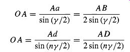
By separately considering the effects of distributing and of chording the winding, reduction factors can be obtained in generalized form convenient for quantitative analysis. The effect of distributing the winding in n slots per phase belt is to yield n voltage phasors displaced in phase by the electrical angle y between slots, 9/being equal to 180 electrical degrees divided by the number of slots per pole. Such a group of phasors is shown in Fig. 3a and, in a more convenient form for addition, again in Fig. 3b. Each phasor AB, BC, and CD is the chord of a circle with center at O and subtends the angle y at the center. The phasor sum AD subtends the angle n y, which, as noted previously, is 60 electrical degrees for the normal, uniformly distributed three-phase machine and 90 electrical degrees for the corresponding two-phase machine. From triangles O Aa and O Ad, respectively,
(Eq. 3)
(Eq. 4)
(Eq. 5)
FIG. 3 (a) Coil voltage phasors and (b) phasor sum.
[...]
2. ARMATURE MMF WAVES
Distribution of a winding in several slots per pole per phase and the use of fractional-pitch coils influence not only the emf generated in the winding but also the magnetic field produced by it. Space-fundamental components of the mmf distributions are examined in this article.
2.1 Concentrated Full-Pitch Windings
We have seen in Section 4.3 that a concentrated polyphase winding of Nph turns in a multipole machine produces a rectangular mmf wave around the air-gap circumference. With excitation by a sinusoidal current of amplitude I, the time-maximum amplitude of the space-fundamental component of the wave is, in accordance [...]
2.2 Distributed Fractional-Pitch Winding
When the coils in each phase of a winding are distributed among several slots per pole, the resultant space-fundamental mmf can be obtained by superposition from the preceding simpler considerations for a concentrated winding. The effect of distribution can be seen from Fig. 6, which is a reproduction of the two-pole, three-phase, full-pitch winding with two slots per pole per phase given in Fig. 1. Coils al and a2, b1 and b2, and c1 and c2 by themselves constitute the equivalent of a three-phase, two-pole concentrated winding because they form three sets of coils excited by polyphase currents and mechanically displaced 120 ° from each other. They therefore produce a rotating space-fundamental mmf; the amplitude of this contribution is given by Eq. B.19 when Nph is taken as the sum of the series turns in coils a1 and a2 only.
Similarly, coils a3 and a4, b3 and b4, and c3 and Ca produce another identical mmf wave, but one which is phase-displaced in space by the slot angle 9/from the former wave. The resultant space-fundamental mmf wave for the winding can be obtained by adding these two sinusoidal contributions.
FIG. 6 Distributed two-pole, three-phase, full-pitch armature winding
with mmf phasor diagram.
The mmf contribution from the ala2bl b2clc2 coils can be represented by the phasor O X in Fig. 6. Such phasor representation is appropriate because the waveforms concerned are sinusoidal, and phasor diagrams are simply convenient means for adding sine waves. These are space sinusoids, however, not time sinusoids. Phasor O X is drawn in the space position of the mmf peak for an instant of time when the current in phase a is a maximum. The length of O X is proportional to the number of turns in the associated coils. Similarly, the mmf contribution from the a3a4b3b4c3c4 coils may be represented by the phasor O Y. Accordingly, the phasor O Z represents the resultant mmf wave. Just as in the corresponding voltage diagram, the resultant mmf is seen to be smaller than if the same number of turns per phase were concentrated in one slot per pole.
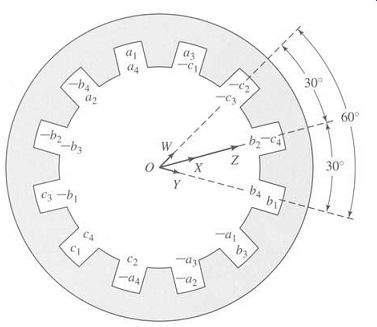
FIG. 7 Distributed two-pole, three-phase, fractional-pitch armature
winding with mmf phasor diagram.
In like manner, mmf phasors can be drawn for fractional-pitch windings as illustrated in Fig. 7, which is a reproduction of the two-pole, three-phase, fractional-pitch winding with two slots per pole per phase given in Fig. 2. Phasor O W represents the contribution for the equivalent coils formed by conductors a2 and –a1, b2 and –b1, and C2 and –c1; OX for ala4 and -a3 -a2, b]b4 and -b3 -b2, and ¢1C4 and -c3 -c2; and O Y for a3 and --a4, b3 and -b4, and c3 and -c4. The resultant phasor OZ is, of course, smaller than the algebraic sum of the individual contributions and is also smaller than O Z in Fig. 6.
By comparison with Figs. 1 and 2, these phasor diagrams can be seen to be identical with those for generated voltages. It therefore follows that pitch and breadth factors previously developed can be applied directly to the determination of resultant mmf. Thus, for a distributed, fractional-pitch, polyphase winding, the amplitude of the space-fundamental component of mmf can be obtained by using kbkpNph = kw Nph instead of simply Nph in Eqs. 19 and 20. These equations then become
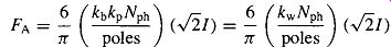
(Eq. 21)
...for a three-phase machine and...
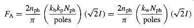
(Eq. 22)
...for a nph-phase machine, where FA is in ampere-turns per pole.
3. AIR-GAP INDUCTANCES OF DISTRIBUTED WINDINGS
FIG. 8a shows an N-turn, full-pitch, concentrated armature winding in a two-pole magnetic structure with a concentric cylindrical rotor. The mmf of this configuration is shown in Fig. 8b. Since the air-gap length g is much smaller than the average air-gap radius r, the air-gap radial magnetic field can be considered uniform and equal to the mmf divided by g. From Eq. 4.3 the space-fundamental mmf is given by [...]