AMAZON multi-meters discounts AMAZON oscilloscope discounts
Valve (vacuum tube) characteristics
The performance of a thermionic valve in any opera ting circuit will be determined by its electrical performance characteristics, which will, in turn, depend both on the mechanical construction of the valve and on the conditions in which it’s used.
Some of these characteristics will relate solely either to the normal, or to the limiting operating conditions, such as the heater voltage and current requirements -- For example 6.3V at 0.3A -- or the maximum anode voltage, anode current and thermal dissipation ratings.
Others will relate to the specific design of the valve, and the shape and disposition of the internal electrodes.
In the case of a rectifier diode, the main parameter is the ease with which current can flow through the valve, usually specified as its 'anode current resistance' , /?a, which is defined as the rate of change of anode current for an increment i n anode voltage, as expressed by the equation:
Ra = dVa dIa (1)
(This relationship is also valid for amplifying valves, but, in these, assumes that the voltage on the grid is held constant.) In a rectifier diode, the magnitude of 7?a will largely determine the effective forward voltage drop across the valve, in its 'forward' or conducting direction. This is influenced principally» for a given heater tempera ture, by the area of the cathode, and the cathode-anode spacing.
In triodes, and more complex multiple electrode valves, /?a is also affected by the presence of grid or other electrode structures in the current path, which will restrict the electron flow from cathode to anode.
However, in these designs, the structure of the valve also affects the degree of amplification which the component will provide. This is called the 'amplification factor' and refers to the maximum voltage swing which could be produced at the anode for a given change in voltage at the control grid, assuming an infinitely high impedance anode load. The amplification factor is denoted by the symbol 'µ' such that:
µ = -dVa / dVg
with L constant (2)
... where the negative sign takes account of the phase inversion of the applied signal due to the valve.
The third common specification is called the 'slope' or the 'mutual conductance' (gm) of the valve - or, more correctly, the 'grid-anode transconductance', since it specifies (in amperes/volt or 'Siemens', though, more usually, mA/V or mS) the change in anode current which is brought about by a change in control grid voltage.
This is expressed mathematically by the equation: d/a dVg with Va constant
(3)
and these three terms are related by the equations: and
(4)
µ = gmRa (5)
.... so that the third can be found if any other two are given in the manufacturer's literature.
Internal grid structures
In a triode, the amplification factor of the valve will be determined by the relative spacings of the grid and the anode in relation to the cathode, and the closeness of the mesh of the grid structure. If the grid is close to the cathode, and the anode is relatively remote, the influence of the grid on the internal current flow will be greater, and the amplification of the valve higher, than if the grid is further away from, and the anode closer to, the cathode.
Similarly, the closeness of the mesh of the grid wire will influence the extent to which an applied negative voltage on the grid will restrict the flow of electrons from cathode to anode, fine meshes giving greater control and vice versa.
However, it will be appreciated that, for a given cathode size, the measures which increase the amplification factor of the valve will also lessen the possible current flow through the valve, and increase its anode current resistance. By and large, therefore, triode valves with high amplification factors will have low anode currents and high impedance values. The comparative structures for grid and anode spacings for high gain, high impedance and low-gain, low impedance triodes are shown in FIGs. 5a and 5b.
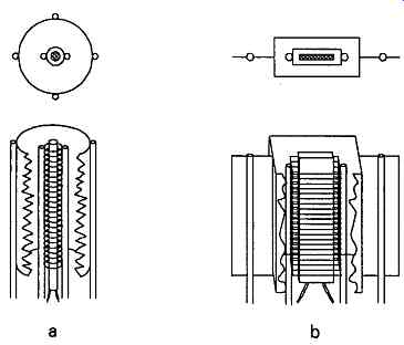
FIG. 5 Comparative grid/anode spacings for high impedance and low impedance
triodes Comparative performance figures for two of the classic small power
'octal' based valve series - the high impedance, high gain, 6SL7 and the
equivalent lower impedance type, the 6SN7 - and the 2A3 power triode show
this difference.
Valve type -- Anode Amplification -- Anode current impedance current factor
(mA typical) (µ) (Ra)
6SL7 6SN7 2A3
Power output triodes, in particular, will have very low amplification factors - typically in the range 5-10 . Also, for such valves to operate satisfactorily with very open mesh grids, which don’t retain a large space charge, very high cathode efficiencies are necessary, and this usually requires the use of a directly heated system.
Since such an electron source will introduce hum modulation of the signal, output triodes with low volt age filaments, such as the 2.5V operated '2A3', were often used. Such filaments would also be thicker and have greater thermal inertia than those of higher working voltage, which would also help reduce thermal modulation of the electron flow.
In spite of the inconvenience in use of directly heated power output triodes, these enjoyed some vogue in high quality audio power amplifiers because of their favorable distribution of distortion products, which were such as to give a 'rich' or 'warm' quality to the sound.
This preference largely disappeared in favor of triode-connected beam-tetrodes, when these latter valves became widely available, and when the increasing use of negative feedback in audio power amplifier designs reduced the amount of residual harmonic distortion anyway.
Screened grid, pentode and beam-tetrode valves
A major problem in the operation of triode valves was discovered as soon as attempts were made to use these valves for RF amplification. In this application, the inevitable inter-electrode capacitance which existed between the grid mesh and the anode plate - typically of the order of 3pF in a small power valve - would cause oscillation, if connected in an RF gain stage circuit layout of the kind shown in FIG. 6, and stable operation would require some form of 'neutralization' of this capacitance, as shown in FIG. 7: an inconvenient circuit elaboration, requiring a tapped anode coil and an adjustable 'neutralizing' capacitor.
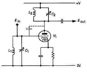
Fig. 6 Inter-electrode capacitance in triode RF amplifier slope.
However, if a further fine mesh grid, (G2), is inter posed between the 'control grid', (G^), and the anode, it’s possible to construct valves in which the internal feedback capacitance is as low as 0.005pF, and RF out amplifier stages built with these valves will be stable up to very high frequencies.
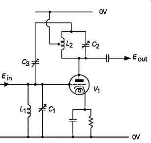
FIG. 7 Neutralized triode RF stage
If this screening grid is connected to the same potential as the cathode, the accelerating field exerted by the positively charged anode upon the electrons within the space charge region will be very small, and very little anode current will flow. Therefore, in order for such a valve to operate, it’s necessary to apply a positive voltage to G2, as well as to the anode.
The actual voltage required for G2 will depend on the valve design, but will generally lie between 0.3 and lx the anode potential, and the relationship between G2 voltage and G2 current will typically be as shown in FIG. 8
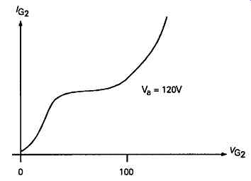
FIG. 8 Screen grid current characteristic in tetrode valve.
This current flow is wasteful, in that it contributes to the power consumption and thermal dissipation of the valve, but performs no useful function. It’s customary in the design of 'screened grid' or 'tetrode' valves, as they are more usually known, to align the grid wires for G2 so that they lie immediately behind those of G1, in order to minimize G2 current.
An incidental advantage of the tetrode construction is that both the anode current impedance, (/?a), (as defined by the extent to which a change in anode voltage causes a change in anode current) and the amplification factor, (µ), are very high, so that very high stage gains can be obtained from such valves.
Typical values are 7?a = 1.5 Megohms, µ= 4500. However, because of the very high values of Ra possible with tetrode designs, it’s more common for the gm of the valve to be quoted in the valve specification, with values in the range 1.5-1 0 being typical.
This allows a rapid estimate of the stage gain (m) to be made, by the use of the relationship:
M = -gm.rL (6)
… so long as the value of the anode load is small relative to the AC resistance of the valve.
A further advantage conferred by the very high values of 7?a in tetrode and similar valves is that there will be very much less 'damping' of any tuned circuit connected in the anode circuit, as a result of the impedance of the valve appearing effectively in parallel with it.
Secondary emission
There is, however, a practical problem which arises with tetrode valves, which is that high velocity electrons impinging upon the anode may eject lower velocity 'secondary' electrons, which will be captured by the positively charged screening grid, if its voltage approaches or exceeds that of the anode.
Since the velocity of the electrons reaching the anode will depend on the anode voltage, secondary electrons will begin to be emitted only when a certain anode voltage is reached, but will be recaptured by the anode once its voltage becomes higher than that of G2, this effect can lead to a 'kink' in the anode voltage versus anode current graph of the kind shown in FIG. 9 While this is relatively unimportant for most RF amplification applications, it would lead to severe output waveform distortions in other uses if large anode (AC) voltage swings were to occur.
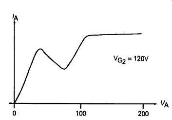
FIG. 9 Anode current characteristic of tetrode valve
Two practical solutions to this problem have been adopted. Of these, the first was to interpose a relatively loose mesh 'suppressor' grid, (G3), between the screen grid and the anode, and to connect this to a suitably low potential, for example, by an internal connection to the cathode. This would cause a decelerating field between G2 and the anode, which would have relatively little effect on the high velocity cathode-anode electron stream, but would effectively discourage the flow of the much lower velocity secondary electrons from the anode to G2.
This was a very successful type of design, which was adopted on a world-wide basis, soon after its introduction, and this layout completely supplanted the normal tetrode RF amplifier valve, except in some battery operated forms.
The high gains and high power efficiencies of the pentode valve also led to its widespread adoption in the period 1935 - 1960 as the output valve in audio amplifiers and radio sets. It did, however, suffer from a substantial amount of third harmonic distortion in its output, and this, by contributing higher frequency components to the output signal, tended to give a somewhat shrill quality to the sound.
The second solution to the problem of the tetrode type anode current kink was to incorporate within the electrode structure a pair of 'beam-confining plates', also typically connected internally to the cathode, of the general form shown in FIG. 10. These operated by modifying the shape of the accelerating electrostatic fields in the region of the anode in such a way as to discourage the capture of secondary electrons by G2.
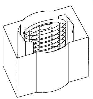
FIG. 10 Use of electron beam confining plates in beam tetrode
The 'beam-tetrode' or 'kinkless tetrode', as this type of valve was known, offered a greater linearity as a power output valve than the pentode, with improved audio quality. It also lent itself readily to triode connection, in which the anode and G2 were connected together. This allowed even lower output distortion figures, though with a lower stage gain and output efficiency.
Such triode connected beam tetrode output stages soon became the principal type used in high quality audio amplifiers, since they offered all the desirable qualities of the triode output stage, but without the problems associated with the directly heated filament construction.
Other circuit arrangements were also developed for use with beam-tetrodes in audio amplifiers, to allow higher output stage efficiencies, but without a substantial worsening of the distortion figures. These layouts are discussed in Section 8.
For RF use, it was not generally felt that the greater large signal linearity of the beam tetrode, in comparison with the normal pentode structure, offered a big enough advantage to justify the extra complexity of the beam-tetrode construction. There were, however, RF beam-tetrodes offered by the Marconi-Osram valve company (the inventors of the design), under the type designations 'KTZ...' and 'KTW...' depending on whether they were sharp cut-off or 'vari-mu' designs.
Variable mu pentodes and tetrodes
With the growing use of 'superhet' type radio receivers, which allowed a very large degree of RF signal amplification, and, consequently, large signal levels at the input to the demodulator, it became practicable to employ 'automatic gain control' (AGC) systems in which the gain of the preceding RF amplifier stages was controlled by the magnitude of the signal at the demodulator.
Special RF amplifier valve types were designed for this use, in which the spiral wire mesh of the control grid (G^) of the valve was wound so that the spacing between the wires became progressively wider to wards one end of the grid structure, as shown in FIG. 11.
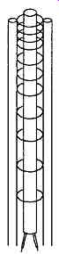
FIG. 11 Grid construction of vari-mu valve
With such a structure, if the negative bias on the grid was progressively increased from its normal operating value, the electron flow would be cut of f at the region where the mesh was close together, and progressively restricted to the wider mesh regions of the grid. Since the fineness of the grid spacing determined the amplification factor (µ) of the valve, as the negative bias was increased, so the µ would be reduced. This allowed the stage gain to be controlled by an externally applied bias voltage, as required for 'AGC purposes. Such valves were called 'vari-mu' types. By contrast, the others were referred to as 'sharp cut-off' types.
Understandably, some proportion of the cathode anode electron stream in a vari-mu valve would al ways pass through the wide mesh part of the grid region, even under the normally low bias conditions, and this would mean that the typical performance of such a valve type would be worse than its sharp cut-off equivalent.
Typical anode current vs. control grid characteristics for a small signal triode, a high power triode, a sharp cut-off pentode, a vari-mu pentode, and an output beam tetrode are shown, for comparison, in FIGs. 12a-12e.
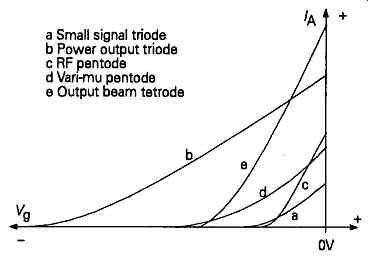
FIG. 12 Anode current characteristics of differing valve types
While vari-mu valves were most commonly found as RF pentodes or beam-tetrodes, the 'hexode' or 'heptode' section of frequency changer types (see below) would also usually be of vari-mu construction.
Other multiple electrode valve (tube) types
In the early days of radio set manufacture, a royalty was charged on the use of valves in such apparatus, which tended to encourage the use of as few valves as possible in these designs.
Later, when the relevant patents had expired, the economics of manufacture still tended to encourage the adoption of valves with multiple internal functions, if only because - at a time when the use of a valve meant the punching of a hole through a metal chassis, the fitting of a valve holder, and the wiring up of these valve holders by workers on an assembly line - the fewer valves installed, the lower the manufacturing costs would be.
In a few cases, the use of a multiple electrode structure was the preferred approach, as For example in the frequency changer stages of superhet radio receivers, where it allowed an internal connection between the oscillator and the mixer portions of the valve. In the bulk of cases, however, the main concern was simply to minimize the valve count.
Obviously, the combination valve types which were produced were mainly those which would facilitate the production of mass produced articles, like radios and television sets; using such combinations as double diode-triodes, or double-diode-pentodes, or twin valves within the same envelope, such as double triodes or triode pentodes; which would provide a substantial market for the valve manufacturers.
Almost all of these multiple valves are now only of academic interest, since, with the exception of the double triode, they are seldom used in any contemporary electronic circuit designs.
Cathode ray tubes
By and large, in low to medium power applications, thermionic emitter systems have been supplanted by various solid state devices, except in very high voltage applications, and even here high voltage MOSFETs are increasingly being used in place of valves. Valves do have advantages, since they are robust and difficult to damage by misuse. However, the major contemporary application for thermionic emitter technology is in the field of cathode ray tubes. These are made in two main types, those intended for electromagnetic and those designed for electrostatic deflection of the electron beam. The former tubes are mainly used for television applications though they are also used in some radar display systems.
In all tubes, an 'electron gun' system is built around the cathode, in order to form an apparent 'point source' of electrons by focusing the emission from the cathode by means of an electrostatic lens. A longer focus electron lens - which can be either electromagnetic, by means of an external 'focus' coil, or electrostatic, by way of a further group of suitably shaped and suitably charged electrodes - is then placed along the barrel of the tube, so that an image of this point source will be formed at the point of impact of the electron beam on the cathode ray tube screen.
For TV use, contemporary practice favors the use of electromagnetic beam deflection but with electrostatic focusing. For use in cathode ray oscillograph tubes electrostatic deflection is invariably used, be cause of the need for very good high frequency response in the deflection system, which would be impracticable with a magnetic deflection assembly.
Diagrammatic representations of the two types of cathode ray tubes are given in FIGs. 13a and 13b.
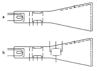
FIG. 13 Cathode ray tubes intended for magnetic and electrostatic beam
deflection.
Deterioration processes
One of the drawbacks in the use of thermionic devices is that they gradually deteriorate in use, giving an effective lifetime of some 2,000 - 10,000 hours of service, depending on the conditions of use, and the extent to which their loss of activity impairs the performance of the circuitry in which they are used.
This deterioration comes about as a result of two main causes - the reduction of emissivity of the cathode, and the gradual loss of vacuum within the envelope. Cathode emission deterioration is an inevitable consequence of the chemical reduction of the initial deposit of barium and other oxide coatings, during the use of the valve, and the loss, by evaporation, of the metallic barium, etc., which appears on the surface of the cathode.
This loss of activity is accelerated by higher than normal cathode temperatures, though the life of a flagging cathode may be somewhat extended by an increase in operating temperature. Filament systems will usually outlast indirectly heated cathode types because of their greater relative efficiencies, as shown in Table
Deterioration due to loss of vacuum is usually most common in higher power valves, and occurs mainly due to outgassing of the anode and grid structures where these have become hot in use, through excessive current flow. It will also occur, though to a minor extent, due to the reduction of the cathode oxide coatings to base metal; normally the 'getter' will absorb this small gas evolution as it arises.
If a valve becomes 'gassy', it will probably exhibit an internal blue-violet glow, due to the ionization of the gas. This ionization will, however, lead to the production of positive ions which will be accelerated towards the negatively charged cathode, and the resultant ionic bombardment may further damage the cathode emission by stripping of f the emissive coating layer.
By comparison, semiconductor devices, if well made and adequately encapsulated, and used within their ratings, will have a virtually indefinite life expectancy, which provided another reason for their use as a 'valve' replacement.