AMAZON multi-meters discounts AMAZON oscilloscope discounts
Early beginnings
Necessity, it’s said, is the mother of invention. This is certainly true of the 'thermionic valve', ‘vacuum tube’, or 'electron tube' as it’s also called, because this invention met an urgent need of the time of its conception, at around the turn of the century, which was for some reliable method for the detection and amplification of very weak radio signals.
This development was a matter of considerable commercial importance, since successful experiments by Marconi had shown the practicability of supplementing or replacing expensive or, as in ship-to-ship, impracticable conductive wire telegraph lines by radio - or 'wireless' - links.
However, the oscillatory frequency of the electromagnetic radiation used for this type of transmission had to be very high, or the efficiency of radiation from the transmitter 'aerial' would be very low. Unfortunately, the use of these very high frequencies meant that the human ear would be quite unable to detect their presence, if the incoming signal current from the receiver aerial was simply connected to a pair of headphones.
The first method which was used by Marconi to detect the presence of this incoming high frequency radiation was the 'Coherer': a device invented in 1890 by the French physicist, Edouard Branly, which consisted of a glass tube with metal end connections, loosely filled with fine metallic powder, which would 'cohere' together if an incoming RF signal was applied to it.
This would cause an immediate increase in the conductivity of the powder filling, and this could be used to cause a pointer deflection in a current meter, but it would then be necessary to tap the glass tube to cause the metal particles to become loose again. In practice, this was arranged by the use of an electric bell-type buzzer to continuously rattle its clapper against the wall of the glass tube.
Though this method did work, and was used successfully as the 'detector' in the first trials of 'Wireless Telegraphy', it was crude and insensitive in action, and could only determine the presence or absence of RF signals. Also, it would obviously have been quite useless in recovering any signal whose transmission was attempted by modulating the amplitude of the signal broadcast by the transmitter.
What was needed was some form of sensitive rectifying system, at the receiver, which would convert the incoming RF signal into a direct current flow, whose size was related to the amplitude of the RF signal.
Unfortunately, no such system was known, which would work at radio frequencies, and this need prompted a great deal of experimentation, of which the most important was that concerned with electronic emission.
The initial observation by Edison, the inventor of the electric filament lamp bulb, in 1880, that the glass envelope of the lamp would darken in proximity to the filament, after prolonged use, was correctly interpreted by Sir Ambrose Fleming as being due to the bombardment of the glass by the thermally emitted electrons; which he called 'thermions'; and Fleming exploited this discovery by the construction of a de vice which consisted of a heated filament, surrounded by a conductive metal plate, or 'anode', housed within an evacuated envelope. An arrangement which he patented in 1904.
Since this device had two elements - the heated filament, or 'cathode' and the anode - he called his device a thermionic 'diode'. The only function which this would perform was to allow current flow in one direction only, and caused him to describe it as a 'valve'. The subsequent introduction, in 1907, of a third electrode - a wire mesh 'grid' between the cathode and the anode - to make a 'triode', was due to an inventor in the United States, called Lee de Forest.
Because this would then allow the flow of electrons between the cathode and the anode to be regulated by the voltage applied to the grid, this device allowed, for the first time, the amplification of small signal volt ages, and set in train the whole development of what we now call 'electronics'. With the introduction of transistors and other semi conductor devices, the thermionic valve has now become largely obsolescent, but there are still a few applications where it has not yet been replaced by more efficient semiconductor components.
These applications include high power, high voltage rectifiers, cathode ray tubes, as used in oscilloscopes and television sets, high power radio transmitting valves, X-ray tubes and the 'magnetrons' used in domestic microwave ovens, as well as a residual use of more traditional small signal amplifying valves in high quality audio amplifier systems. It’s still useful, therefore, to possess some understanding of the basic technology.
The modern thermionic valve (tube)
The basic structure of a thermionic valve consists, in its essentials, of an evacuated glass or metal envelope, within which is mounted a cathode, as a source of electrons, and an anode (though in some cases there may be more than one) maintained at a positive potential with respect to the cathode, to attract these electrons, and thereby cause a current flow through the valve. Because the electrons are negatively charged, they will be repelled if the anode is itself negatively charged. The current flow through the valve can, there fore, only be in the direction from the cathode to the anode.
A simple valve, having just a cathode and an anode, can be used to 'rectify' an alternating current flow to convert it into a series of unidirectional current pulses, as shown in FIG. 1a. A typical application, as a rectifier in a power supply circuit, is shown in FIG. 1b.
In an amplifying valve, one or more grids are inter posed between the cathode and the anode, and the potentials applied to these will increase or reduce the flow of electrons reaching the anode. By means of these electrodes, the current flowing through the valve, which can be as large as the design permits, may be directly controlled by some externally applied volt age, and this permits a very high degree of power amplification.
In such an amplifying valve, the grid which is closest to the cathode will normally be negatively charged with respect to it, and this will cause a cloud of free electrons to accumulate between the cathode and the grid. This electron cloud is called the 'space charge' and serves as a reservoir of electrons, to permit high anode currents to be drawn for brief periods.
This grid, if negatively charged, will usually draw no electronic current, and therefore appears - from the point of view of the external circuitry - as an open circuit. This electrode is therefore normally used as the 'control grid' of the valve.
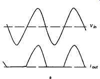
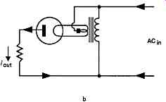
FIG. 1 Use of thermionic diode as rectifier
Various different structures of thermionic valves have been evolved for specific purposes, and some of these are discussed in detail below. However, the element which is common to all of these designs is the cathode, as the source of electrons, and the characteristics of this part of the valve and the mechanisms which influence the emission of electrons are of great importance in the operation of the device.
Thermionic emission
The energy due to thermal agitation of an electron within a metallic conductor increases as the square of the absolute temperature, (°K), so that, if a metallic body is heated, in vacuum, a temperature will be reached at which the kinetic energy of the electrons will exceed the level, known as the 'work function' of the metal, which is needed for an electron to escape from the electrostatic forces which bind it to the atomic nucleus.
Above this temperature, an increasing number of electrons will escape into the space surrounding the metallic body, until the increasing positive charge appearing on the body, as a result of the loss of electrons, prevents the escape of any more.
The number of 'free' electrons which surround the hot metallic body is thus the result of a condition of dynamic equilibrium between the thermal energy of the electrons and the residual positive charge which their departure has left on the surface from which they have escaped. As noted above, this electron cloud is known as the 'space charge.' If a positively charged conductor is mounted, in vacuum, in proximity to this space charge, an electronic current will be drawn from this cloud of electrons, which will be replenished from the heated body to maintain the equilibrium. The total current which can be drawn reaches a saturation level when the space charge region is stripped of electrons, and this is dependent on the temperature of the metallic body.
In a thermionic valve, the region emitting the electrons is known as the cathode, or sometimes, loosely, as the 'filament', in those cases where the emitting surface and the heater element are combined in the same component, rather than being formed by a metallic tube, heated by an internal bundle of resistance wire.
The actual thermal energy which is needed to cause electrons to escape from a metallic surface depends on the atomic structure of the metal itself, but very high temperatures may be required, as is shown in Table 1, for pure tungsten, in a high vacuum. The figures quoted, as also those of Table 2, are due to Williams and Prigmore. (Electrical Engineering, 1963, Heinemann.)
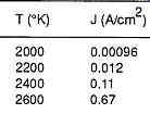
Table 1 Electronic emission (J) from metallic tungsten in vacuum
Various techniques have been evolved to reduce the required temperature for electronic emission. Of these, one of the simplest was to incorporate a small amount of thorium oxide in the powder mix from which the tungsten filament was sintered, and then to heat the filament in an atmosphere of acetylene to coat the surface with a layer of tungsten carbide.
This carbide layer performed two functions: to re duce metallic evaporation from the filament - which would, in due course, cause localized thinning and subsequent fracture - and to react chemically with the thorium oxide to produce an atomic thickness layer of metallic thorium on the filament surface. Unfortunately such 'thoriated tungsten' filaments (dull emitters) tend to be more brittle, and more easily broken by mechanical shock, than those from pure tungsten, known as 'bright emitters'. The second major technique is to coat the filament, or cathode tube in the case of an indirectly heated valve, with a thin layer of nickel, on which is subsequently deposited a coating of mixed barium, strontium and calcium carbonates. These are subsequently reduced to their respective oxides by heating, during the manufacturing process.
In operation, the barium and other oxides in contact with the nickel substrate are reduced to the base metal, and this diffuses outwards through the oxide layer to the cathode surface, where it contributes to the total emission of electrons. Any residual gas in the valve envelope may however combine with the reactive metal surface and render it inactive.
Although these ‘oxide coated' cathodes offer much higher efficiencies in terms of output current for a given energy input to the heater, and can provide a copious flow of electrons to sustain the space charge, they have a more limited operating temperature range than either bare tungsten or thoriated tungsten cathodes.
This is because the lower operating temperature is determined by the escape energy required by the electrons, while an upper limit is set by the need to avoid significant evaporation of the relatively volatile cathode metals from the surface. If such emissive metals are allowed to contaminate the grids or the anode, this could lead to secondary emission, and this can lead to a number of problems, as discussed below.
The relative efficiencies of the various practicable cathode types, at various operating temperatures, are shown in Table 2 .
In an oxide coated cathode, the total current drawn from the cathode (space charge) must be substantially less than the possible theoretical maximum if a long operating life is required. If 'saturation current' is drawn, that is if the space charge cloud is entirely stripped of its free electrons, the cathode surface may be damaged.
Such oxide coated cathodes are also much more easily damaged by 'sputtering', which is a term given to the explosive removal of surface particles by bombardment by energetic gaseous ions. These ions will be formed if a rapidly moving electron collides with a molecule of gas, and will be both positively and negatively charged. Those with a positive charge will be accelerated towards the cathode and will cause physical damage on impact if they are sufficiently energetic.
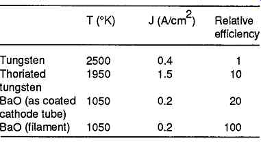
Table 2 Thermal efficiencies of cathode structures
This is particularly likely to happen if high anode voltages are employed, since there will always be a small amount of residual gas within the valve envelope, due to outgassing of metal grids and anodes within the valve - especially if these are allowed to overheat - or arising from the reduction of the oxide coatings on the cathode itself.
To reduce the possibility of sputtering, all normal electronic valves employ an internal gas-absorbing layer, known as a 'getter', made up from highly reactive alkali metals, which is held in a small basin within the envelope of the valve. After the valve envelope has been evacuated and sealed, the cup holding the gettering compound is heated by an eddy current generator, to evaporate the gettering layer onto the inside of the envelope, well away from the active regions of the valve.
If the envelope should crack, and let in air, the loss of the dark mirror-like appearance of the gettering layer is usually the first visible symptom of trouble.
The likelihood of damage due to the bombardment of the cathode, as a result of the ionization of residual traces of gas, limits the voltages which can be applied to the anode, as shown in Table 3 This leads to the use of either thoriated tungsten or plain tungsten filament 'bright emitter' valve types for high power transmitter applications, where high anode voltages are needed
(Note. Oxide coated cathodes are, however, usable in oscilloscope tubes, even at much higher voltages than this figure, because it’s possible to design the internal electrode structure of the tube so that returning positive ions will be physically intercepted before they reach the cathode.)
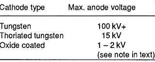
Table 3 Anode voltage limits for various cathode types
The superior thermal efficiency of the 'directly heated' oxide coated filament structure leads to this type of cathode being used exclusively where low power consumption is essential, or where, as in power amplifier triodes, the mesh of the grid is too coarse to permit a large space charge to accumulate.
Indirectly heated cathode systems
The major problem with using a heated filament, as the cathode, is that the voltage between the control grid and the filament will vary along its length, and will alter if the voltage applied across the filament changes.
If the filament is heated by an AC voltage, this will then cause an AC modulation of the current through the valve in synchronism with the AC filament potential.
Also, unless the filament is substantial in size, its temperature, and its electronic emission, will vary in sympathy with the applied alternating filament voltage, and these effects may introduce a large 'hum' component into the output signal.
Valves intended for use in equipment where the cathode heater power is derived from an AC source therefore employ, with very few exceptions, a cathode structure of the type shown in FIG. 2, in which a resistive heater, formed either as a twisted helix, or as a simple folded bundle, is given a robust insulating coating of some refractory material - usually alumina - and is then inserted into a separate tubular metal cathode sleeve.
The general construction of typical cathode systems is shown in FIGs. 3a - 3c.
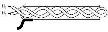
FIG. 2 Heater system for indirectly heated cathode
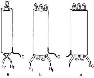
FIG. 3 Methods of construction of individually heated cathodes
To avoid fluctuations in the cathode temperature in sympathy with the heater current, normally supplied at either 50 or 60Hz, the thermal inertia of the cathode system is usually chosen to give a thermal time constant in the range 20-60 seconds. Such valves there fore require a warm-up time before they will operate.
Care is taken in the design of the assembly to keep leakage currents between the cathode tube and the heater wire to a very low level, and also to prevent the emission of electrons from the heater element, particularly as a result of contamination by evaporation from the cathode surface. However, where this factor is critical, it’s prudent to arrange that the mean heater voltage is somewhat positive with respect to the cathode.
Anode structures
In its simplest form, the anode will simply be a metal cylinder surrounding the cathode, at a separation determined by the conducting impedance which it’s required that the valve should have, and with an area which is adequate to radiate the heat generated by the kinetic energy of the electrons which impinge on it.
The most common metal from which the anodes are made is nickel, and the outer surfaces of the anode will frequently be blackened to assist in the dissipation of radiant heat.
It’s also important that the whole internal structure of the valve is held rigidly in place, to prevent mechanical vibration of the electrode assembly from modulating the output current. This can cause audible 'ringing' sounds in audio systems if the envelope of an amplifier valve is struck, and is referred to as 'microphony'.
Because of the need for the maximum rigidity in construction, anode and grids are most commonly made in a rectangular cross-section, supported at their edges or corners by rigid metal rods. These are mounted in the glass seat or 'pinch' at the base, and held in place by one or more stiff mica plates, wedged into the envelope of the valve. Typical construction styles are shown in FIGs. 4a- 4d, for diodes and multiple electrode valves.
a. Diode
b. Power rectifier
c. Mulitple electrode valve
d. Output beam tetrode
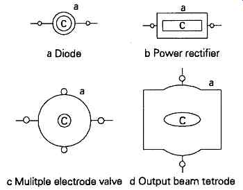
FIG. 4 Typical styles of anode construction.
In a rectifier diode, the normal requirement is for as low a conducting impedance as possible, so the anode will be formed in a very tight cylinder around the cathode, at the smallest spacing which is compatible with the avoidance of inadvertent internal short circuits or spark over. The metal of the anode is usually extended on either side of the cylindrical section in order to help radiate any heat evolved.