AMAZON multi-meters discounts AMAZON oscilloscope discounts
...
For convenience, the various components used in electronics are usually divided into two descriptive categories, 'active' and 'passive', mainly depending on whether any additional energy is introduced into the circuit by their action. Active components include thermionic valves, together with operational amplifiers, transistors, diodes, and other semiconductor devices, leaving the term passive to describe all the remaining elements of the circuit.
Building any electronic circuit will nearly always require the interconnection of a variety of both these kinds of components, and the way they interrelate will affect the functioning of the design. So, although passive components may seem relatively unexciting in their characteristics the correct choice of these can be important in achieving the intended circuit performance.
Resistors
The purpose of these components is to produce a voltage drop (V = IR) which is proportional to the current flow through the device. Ideally, the resistance value of such a component, quoted in ohms, should be constant, independent of time, temperature, current flow or voltage across it - so long as the resultant thermal dissipation (W = VI) is within the rating of the device - or the frequency of the applied current.
Most modern components approach fairly closely to these requirements, but earlier, rather less satisfactory component types may still be found in existing equipment. The broad categories are: Wirewound
These were the earliest form of resistor, and are still widely used where relatively high power dissipation resistor types are needed. As the name suggests, these resistors are made by winding a number of turns of some suitable resistive wire, in a spiral, on a convenient hard, insulating substrate-- normally a ceramic rod or tube -- in the general form shown in FIG. 1.
The wire will nearly always be made from a metallic alloy, chosen for its independence of resistance value as a function of temperature, over the normal working temperature range: some typical alloys are listed in Table Since these alloys are usually difficult to solder, tinned copper wires (or terminals, in the case of high power components) are usually either welded or crimped on to the wirewound element, to assist in connecting the resistor into the circuit.
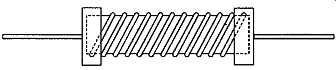
FIG. 1 Basic construction of wire-wound resistor
Table 1 Resistive characteristics of metals and alloys
Metal or alloy Relative resistivity Temperature
(copper = 1) coefficient (ppm r C) Aluminum Copper Constantan (= Eureka)
Karma Manganin Nichrome Silver 1.63 1.0 28.45 77.1 26.2 65.0
0.94
+0.0004
+0.00039
+/-0.000022
+/-0.000002
+/-0.000002
+/-0.000017
+0.0004
The resistance of any conducting wire is proportional to its length and its specific resistivity, p, and inversely proportional to its cross-sectional area. This leads to the equation
R- pL
' A (1)
If the length, L, and the area, A, are measured in meters and square meters, the resistivity, p, will have the form ohm-meters.
The resistive characteristics of aluminum, copper and silver are included for reference, but these materials will only be used where a low resistance is necessary. The other materials listed are designed specifically for use in wirewound and other resistor applications.
Since, in a practical wirewound resistor, it’s desirable that the resistor should have a stable resistance value, one of the low temperature coefficient alloys will be chosen for its construction, such as 'Constantan' or 'Karma'. Also, since it’s preferable not to have to wind more turns of wire on the former than one must, a material with a high value of specific resistivity is also desirable.
A low temperature coefficient of resistivity will usually be associated with a low coefficient of expansion, and the thermal characteristics of the 'former' (the rod on which the resistor is wound) will be matched to that of the wire, so that it neither becomes slack on heating, nor stretched -- which would happen if the former expanded more than the wire -- since this would bring about a permanent change in the resistance of the wire.
The winding will usually be anchored in place with a coating of some hard, heat and moisture resistant, insulating material, except in the case of variable resistors or potentiometers, where an uncoated track must be left for contact with the slider.
A simple, multiple turn, wirewound resistor will also offer a measure of inductance, and where it’s important that this should be kept to a low value, 'non-inductive' wirewound resistors are made by periodically reversing the direction of winding.
However, most commercial wirewound resistor types are inductive, and the circuit designer must allow for this characteristic.
Where a component having a high power dissipation, but a low self-inductance is required, it will probably be necessary to find some other resistor type, such as one of 'metal glaze' construction.
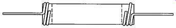 FIG. 2 Early form of carbon composition rod resistor
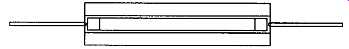
FIG. 3 Improved form of carbon composition rod resistor
Carbon composition:
Another early form of resistor, illustrated in FIGs. 2 and 3, is made by baking an appropriately chosen blend of powdered graphite and clay to form a solid rod having a suitable value of resistance. Connections to this rod are made by spraying or dipping the ends of the rod, to give a solderable metallic coating to which wires can be attached.
The whole rod will then, typically, be impregnated with wax in an attempt to prevent the ingress of moisture which will alter its resistance value, or worsen its already poor long-term stability of value.
Since the only way of controlling the resistance value of the component is by means of its physical dimensions and the composition of the mix, prior to firing, the final value of the resistor will be a matter of guesswork on the part of the manufacturer. This means that the resistors must be sorted, after firing, end-cap metallization and impregnation, in order to select the required values.
In practice, this means that a given value, +/-10%, will be just that, since all those which have a closer approach to the required value will have already been selected out.
In the better forms of this component, the resistive rod will be enclosed in a ceramic insulating tube, to prevent inadvertent short circuits with adjacent components.
As noted above, all resistors of this general type have a poor stability of resistance value, which will change somewhat when they are soldered into a circuit, or if they become hot in use. They also have a relatively high 'excess' noise figure. Fortunately they have now been almost completely replaced by better types.
FIG. 3 Improved form of carbon composition rod resistor
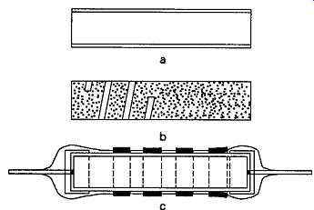
FIG. 4 Stages in construction of a tracked carbon film resistor
Carbon film
This is now a very common constructional method for small wattage (0.125 - 2W) resistors, and is based on the use of a ceramic rod on which a hard and durable surface film of carbon has been deposited, in the manner shown in FIG. 4a. The initial range of values for such a resistor can be controlled by the choice of its physical dimensions, and the thickness of the carbon film.
Resistance values higher than that initially given by the basic manufacturing process can then be obtained by grinding a coarse spiral gap through this film layer, as shown in FIG. 4b. Since it’s normal practice to monitor the resistance value of the component while this track is being cut, the accuracy of the final value will be determined mainly by the precision of setting of the track cutting apparatus.
External connections are made by crimping end caps on to the ends of the rod, and connecting wires are normally welded on to these caps. The whole unit is then given a hard protective coating, prior to painting with a colour coded pattern to denote its resistance value, to produce a component of the type shown in FIG. 4c.
This type of resistor has excellent long term and thermal stability characteristics, and normally offers a high degree of precision in respect of its nominal value. It is, however, being increasingly replaced in the manufacturers' catalogues by resistors having an identical physical structure, but with the resistive film made from a thin vacuum evaporated nickel chromium alloy, known collectively as 'metal film resistors'. Metal oxide film resistors
These are similar in form to the carbon film types, but with the carbon layer on the ceramic former replaced by a thin layer of tin oxide. This can be fused on to a borosilicate glass or ceramic rod substrate to give a robust and tenacious coating, having very good electrical characteristics.
Since it’s somewhat more expensive to make this type of resistor than those based on a metal film layer, these metal oxide resistor types are now becoming rarer, though they are still used where certain military specifications demand very high reliability, since the relatively thick tin oxide layer is more resistant to impact damage or corrosion under high humidity conditions.
Metal film resistors
The past two decades have seen an enormous increase in the use of vacuum evaporated metal films, for applications ranging from packaging materials to integrated circuits, and this growth of technical competence has greatly reduced the cost of this type of process, so that it’s now not significantly more expensive to make a metal film resistor than a carbon film one.
Such metal film components have a lower tempera ture coefficient of resistance (+/- 50 parts per million, per degree Celsius), in comparison with the carbon film types (+/- 150ppm), as well as a slightly lower 'excess' noise figure and a rather better ability to survive short term overloads. Since they are now available at a comparable price to their carbon film equivalents, these have now become the most popular low-power resistor type in all new electronic apparatus.
These resistors are available in power ratings from 0.125W-1W.
Metal glaze resistors
These components are similar to the metal oxide types, except that the resistive coating on the ceramic core is formed from a relatively thick fused layer of glass and metallic powders. The increased thermal inertia of this layer gives the component a better ability to withstand surge conditions, or short term overloads than the metal film types. Typical thermal coefficients for this design lie in the range +/-150 to +/-250ppm. Such resistors are available in power ratings from 0.125W to 3W.
These resistor types are also available as groups of resistors, either entirely separate or with one end of each connected to a common line, mounted together in a single encapsulation, and with their connections brought out in an identical manner to the 'DIL' (dual in-line) integrated circuit package, or the 'SIL' (single in-line) equivalents shown in FIG. 5.
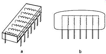
FIG. 5 Two of the available forms of DIL and SIL thick-film resistor blocks
Temperature-dependent resistors
These devices are normally called 'thermistors' and are designed so that they will have a very high thermal coefficient of resistance, either positive or negative, for use as temperature sensing elements, or in protective or power control applications.
The earliest forms of negative temperature coefficient devices consisted of fired pellets of clay containing various proportions of silicon carbide, but these components have been the subject of intensive commercial development and a wide range of inter metallic compounds, such as nickel magnetite, is now employed, to provide specific electrical characteristics.
Of the negative temperature coefficient (NTC) types, the most common forms are the rod, disc and bead types, together with the vacuum envelope encapsulated bead types used for amplitude control in oscillators and the miniature probe-mounted devices used for temperature probes. These are illustrated in FIG. 6.
The relationship between resistance and tempera ture of these devices is shown in FIG. 7, for some typical NTC thermistors.
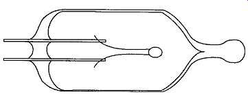
FIG. 6 Vacuum envelope miniature bead thermistor
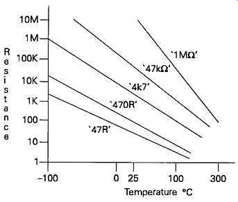
FIG. 7 Family of resistance-temperature curves for thermistors of various
types and compositions
Positive temperature coefficient (PTC) components are generally designed so that they have a low value of resistance up to some critical turn-over (or reference) temperature, beyond which the resistance will increase rapidly. They are made from a sintered mix ture of lead, barium and strontium titanates, and the turn-over temperature is controlled by adjustment to the composition of the mix, and the firing conditions.
Their physical form is similar to that of the NTC disc thermistor types.
A major application for these PTC devices is in over-temperature protection for components such as transformers and motors - by incorporating the device within the physical structure of the component to be protected, and connecting it, electrically, in series with it, as shown in FIG. 8. Such PTC devices can also be used as current limiting components.
The relationship between resistance and tempera ture and current for a given applied voltage is shown in FIGs. 9 and 10.
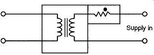
FIG. 8 Overload protection by means of a positive temperature coefficient
thermistor
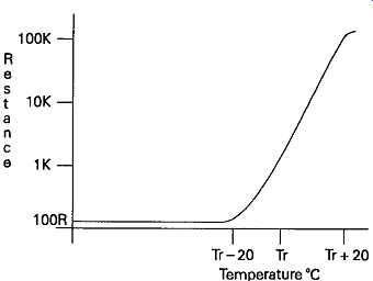
FIG. 9 Resistance vs. temperature for a PTC thermistor
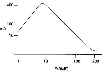
FIG. 10 Current vs. applied voltage for a PTC thermistor
A similar, but rather more restricted, range of positive resistance coefficient, as a function of current, is shown by a vacuum envelope tungsten filament lamp bulb, and this effect can sometimes be employed to provide an inexpensive power or voltage control sys tem.
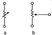
FIG. 11 Variable resistor and potentiometer
Variable resistors and potentiometers
The variable resistor is, as its name suggests, a two terminal device, while the 'potentiometer' or potential divider is a three terminal one. These have the circuit forms shown in FIG. 11a and 11b. Because of its greater versatility (in that by ignoring one terminal, a potentiometer can always be used as a variable resistor) the potentiometer is by far the most common form found in electronics.
These components are available in an exceedingly wide range of physical forms, tailored to various practical applications, and a wide range of constructional types, of which the most common is the semi-rotary design, with a part circular track, as shown in FIG. 12.
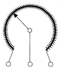
FIG. 12 Schematic construction of potentiometer
The cheapest of these use carbon film tracks, with the sliding contact taking the form of a short graphite rod, to minimize surface wear on the track, since this will lead to electrical noise in operation, and ultimately terminate the useful life of the component.
Better quality potentiometers use conductive plastics, or 'cermet' (i.e. metal glaze thick film) tracks, in the interests of lower noise and surface wear rates, or wirewound construction, with the resistive wire wound on a thin former, as shown in FIG. 13, to minimize the cross-sectional area of the core, and consequently the winding inductance.
Permissible thermal dissipations will range from 0.2W for a small printed circuit board mounted pre-set component, up to many tens of watts for a large power control unit. In normal small-signal electronic circuitry, the maximum power ratings for a panel mounted control potentiometer is likely to lie in the range 2-3W. For longevity, it’s desirable to keep the total dissipations, and, particularly, the current flow drawn from the slider, to as low a value as practicable.
Two normal 'laws' are used to specify the relation ship between the rotation of the shaft of a rotary potentiometer and the resistance between the slider and the beginning of the track.
These are 'linear', in which there is a linear relation ship between rotation and resistance value, and 'log' or 'audio', in which the resistance characteristics of the track are chosen so that there will be an approximately constant relationship between the rotation of the control and the sound output level from an audio amplifier in which the potentiometer is used as a 'volume' or 'gain' control.
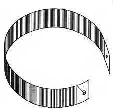
FIG. 13 Resistance element for a wirewound potentiometer
It’s notoriously difficult to produce potentiometers, with such non-linear or graded tracks, so that the actual resistance for a given degree of shaft rotation is the same from one supposedly identical unit to another.
This leads to the problem that, in audio amplifiers, whose gain is controlled by a twin-gang potentiometer, the balance between the output sound levels of a 'stereo' system may vary as the gain control is altered. In high quality audio equipment, the control of output sound level may therefore be achieved by the use of a multiple position switch, between whose contacts selected values of fixed resistor are wired.
Spurious effects
Unwanted characteristics are not likely to be of major importance in the case of these components. Although all resistors are likely to exhibit some degree of 'parasitic' series inductance, this can generally be ignored, except in the case of the larger value wire wound types, or in very high frequency (VHF) applications, where the inductance of the connecting wires must also be considered. There will also be an element of parallel capacitance, but this, again, is unlikely to be trouble some except at VHF. All resistors will introduce some thermal noise, as a direct function of their resistance value, and this is defined by the equation
V = ^AKT/Sß (2)
where V is the mean noise voltage, K is Boltzmann's constant (1.38 x 10~23), T is the absolute temperature (° Kelvin), R is the resistance value, and Af is the effective bandwidth of the circuit in which the noise is measured. This means, for example, that a 2k7 resistor would introduce a mean noise voltage of 0.95µ?, RMS, into an audio circuit with a measurement band width of 20kHz.
A group of noise voltage curves is shown in FIG. 14
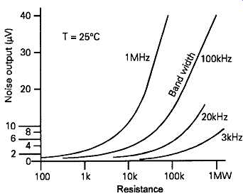
FIG. 14 Resistor thermal noise for various measurement bandwidths
However, in addition to this unavoidable contribution to the circuit noise, purely due to the resistance of the component, there is also the phenomenon of 'excess' noise. This is a function of the way the resistor is made, and of the composition of the materials used.
It’s due to a variety of causes, including the trapping of electrons by 'holes' introduced by impurities and random electro-chemical potentials. Noise can also be introduced by piezo-electric and tribo-electric effects.
Resistors can also suffer from voltage dependence of resistance value -- quite apart from any thermal effects due to current flow, and consequent heating -- and also, sometimes, from asymmetry of resistance value, due to imperfections at points of mechanical contact. The better quality modern components are much less prone to these problems than earlier carbon composition types.