AMAZON multi-meters discounts AMAZON oscilloscope discounts
... << cont from part 1
Capacitors
If two conducting bodies are brought into proximity with one another, a capacitance will exist between them. This has the effect that, if a potential is applied to one of these bodies, it will cause an electronic current flow into, or out of, the other body until a state of equality of charge, of opposite potentials, is established on both of these bodies, as shown in FIG. 15.
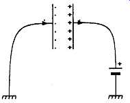
FIG. 15 Charge separation between plates of a capacitor
This has the useful effect that a change in potential may be communicated from one conductor to another without the need for a direct connection between them.
For any given applied potential, the quantity of current which will flow in a circuit containing two such separated conductors will depend on the capacitance between them, and this is dependent on their relative areas, their proximity to one another, and the characteristics of the material which separates them.
The presence of any material between the conducting bodies will always have the effect of increasing the capacitance between them, by comparison with that which would exist if the conductors were separated by a vacuum, and this characteristic of the material inter posed between the conductors is called the 'dielectric constant' of the material, and is conventionally denoted by the symbol T . The capacitance of any arrangement of conducting plates separated by an insulating (dielectric) layer is defined by the equation
C=M
kA
(3)
where C is the capacitance value (specified in farads or some fraction of a farad), M is some constant, related to the physical form of the capacitor, and the units in which the dimensions are specified, A is the plate area, k is the dielectric constant of the material from which the insulating layer is formed, and d is its thickness.
For a practical capacitor, neglecting end-effects, this formula can be re-written as C - kA/1132d (pF), for dimensions in centimeters.
From this equation it can be seen that the capacitance of a capacitor increases in direct proportion to the area of the plates, and the dielectric constant of the insulating layer, and in inverse proportion to the thickness of the insulating material between the conductive plates.
On the other hand, the maximum voltage which such a capacitor will withstand is proportional to the thickness of the insulator and to its dielectric strength.
It will be seen from equation (3) that the dielectric constant, otherwise known as the 'specific dielectric permittivity', of the insulating material has a direct effect on the capacitance of the arrangement, and is as important as the thickness of the insulation in this respect.
Table 2 Dielectric properties of common insulating materials
Material Ceramics (depending on Glass Mica Paper (dry)
Polycarbonate Polyester Polyethylene Polypropylene (oriented)
Polystyrene Dielectric constant (at 1kHz and 20° 5 - 50,000 type)
7- 8 5.5-8 4.5-4.7 2.8-3.0 2.8-3.2 2.25 2.20 2.5 O)
Breakdown strength (volts/mil)
100-1000 500 - 2000 600-1500 500-1000 750-1200 2000 - 4000 1000 1500 800-1000
As a reference standard, the dielectric constant of a vacuum is given a value of unity. Most gases, such as air, also have values which are very close to unity. ( For example, dry air has a value of k = 1.0006). All solid and liquid materials will have dielectric constant values which are greater than this, and the characteristics of some of the more common dielectric materials are given in Table 2.
The dielectric constant should always be quoted at some specific frequency, since in all dielectric materials this property decreases in value as the applied frequency is increased. The k value for all materials will also depend on their exact composition and method of manufacture, and will change somewhat with temperature, or applied voltage.
Additionally, all dielectric materials, other than a vacuum, will experience some inter-molecular electronic re-arrangement under the influence of the applied electric field, and this leads to some absorption of energy from the system. This is proportional to frequency, in the case of an alternating electric field, and is known as the 'dielectric loss' or as 'tan d', where 6 is the alteration in phase angle of the resultant current through the component, under AC conditions, due to the reactive and resistive (lossy) components of the current. The effects of this will be examined later.
For practical use, in electronic circuitry, capacitors are made by a variety of methods, described below, with the aim of producing reliable, robust, compact components with precise and reproducible capacitance values, and at a competitive cost.
These can be divided into three broad categories, 'polar' or 'electrolytic', 'non-polar' and variable.
In electrolytic capacitors, the insulating film between the two conductors is formed by electro-chemical action between a conducting electrolyte, and one or a pair of metallic bodies. This can result in a very high capacitance value, but such a capacitor will be sensitive to the polarity of any potential applied across it.
Non-polar capacitors are made from metallic foils or surface coatings, separated by some suitable insulating dielectric, which will normally be either a thin plastics film, a thin layer of mica or a fired ceramic molding.
Variable capacitors are most commonly built with adjustable metallic plates, mounted parallel to one another, which can be moved into or out of mesh, while preserving an air gap between them. This allows the area of the plates opposite to each other to be continuously varied, which alters the capacitance between them.
Electrolytic
The most common type of electrolytic capacitor is that made from a spiral of aluminum foil, with the turns separated by a layer of some absorbent material, such as cloth or paper, impregnated with some proprietary solution or gel, the whole assembly being enclosed in an aluminum container to give a structure of the general form shown in FIG. 16.
On the initial passage of current through the capacitor, a thin, continuous (anodized) film of aluminum oxide, which is a good insulator, will form electrolytically over the whole exposed surface of the positively connected foil, as shown in FIG. 17, and the cur rent flow will fall to a near zero level.
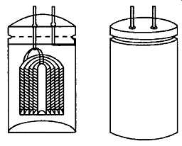
FIG. 16 Typical can-type electrolytic capacitor (spiral wound foil/separator)
This process is known as 'forming', and the voltage applied at this stage determines the maximum voltage at which the capacitor may be operated. It may be done, during assembly, using the electrolyte within the capacitor, or the oxide film may be formed, prior to assembly, using a boric or phosphoric acid anodizing bath.
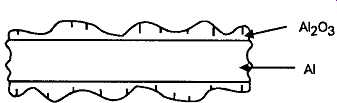
FIG. 17 Section through anodized oxide layer on aluminum foil
Any residual perforations in this oxide film will be automatically healed, by further electrolytic action, during use, and because the anodized oxide film is very thin, such capacitors have a very high capacitance for a given volume.
The capacitance of the units may be increased still further by increasing the effective surface area of the foils by etching the anode foil prior to forming, though such 'etched foil' electrolytics have somewhat lower peak charge/discharge current capability than the plain foil ones.
In early capacitors of this type, the electrolyte, which forms the cathode of the capacitor, would be a water/glycol mix, containing an ionic compound such as boric acid, to increase its conductivity and viscosity, and promote self-healing anodization.
However, internal corrosion could be a problem, so more modem types use organic electrolytes, such as di-methyl acetamide, methyl formamide, or butyro lactone. Some additional gelling agent may also be included to lessen the possibility of leakage from the impregnated paper separators.
Aluminum electrolytic capacitors are available in capacitance ranges from 0.47|uF - 200,000|jF, and voltage ratings from 2.2V - 470V, though the larger capacitance values will generally only be available at the lower end of the working voltage range.
Such capacitors are widely used where high values of capacitance are needed, such as in supply line decoupling, and power supply applications. Unlike non-polar capacitors, there will always be some leak age current through an electrolytic capacitor, and this will vary with the applied voltage in the manner shown in FIG. 18.
Recent technology has also led to the development of small 'solid dielectric' aluminum 'bead' capacitors, known as 'SAL', based on a manganese dioxide 'solid electrolyte'. These are very similar in characteristics to their tantalum bead equivalents, but are much less expensive. Their physical construction is shown in FIG. 19a.
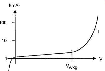
FIG. 18 Leakage current in large capacity electrolytic capacitor
Epoxy resin encapsulation; folded aluminum strip
Mn02 electrolyte; Conductive epoxy sheath
Epoxy resin encapsulation; sintered tantalum bead impregnated with Mn02
Silver foil outer sheath
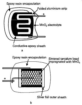
FIG. 19 Constructional forms of solid aluminum (SAL) and tantalum bead capacitors
Like the tantalum bead types, these are physically very small, and offer capacitance ranges of the order of 0.1uF- 100uF, at relatively low working voltages.
They are claimed, moreover, to have a much longer life expectancy, prior to failure, than the equivalent tantalum bead components, since the normal tantalum bead capacitor failure mode - that of crystallization of the tantalum pentoxide layer- is absent in aluminum systems.
Since the leakage currents of these particular types of capacitor are usually very low, at voltages below their rated working level, they can be used for inter stage coupling in electronic amplifier circuitry.
However, although solid dielectric electrolytics are better, in this respect, than the more traditional forms, all aluminum electrolytic capacitors tend to deteriorate somewhat, in respect of their capacitance, and leakage current characteristics, if they are held for long periods without any applied polarizing potential, and this fact must be borne in mind in the design of the circuitry.
The other widely used type of electrolytic capacitor is that in which the anode foil is made from tantalum, on which a thin anodized film of tantalum pentoxide (Ta205) has been formed electrolytically. These capacitors are made in very similar forms to the aluminum foil equivalents, but at a much greater cost.
In the form most directly equivalent to the aluminum electrolytic, these capacitors take advantage of the chemical inertness of the oxide layer, and use a strongly ionized electrolyte, such as sulphuric acid, or lithium chloride solution, whose high conductivity lowers the equivalent series resistance of the component.
Since the tantalum oxide film is so inert, and physically very robust, tantalum electrolytics will generally offer a lower leakage current than their aluminum equivalents, and are also much more resistant to the deterioration of the oxide layer during storage or use under zero voltage conditions.
Apart from their high cost, such wound-foil tantalum electrolytic capacitors would be very suitable for use in audio circuitry, and this has encouraged the development of a lower cost version of these components, based on a pellet of sintered tantalum powder, impregnated with a solid electrolyte of manganese dioxide, formed in situ by the 'pyrolitic' (i.e. by heat) reduction of manganese nitrate.
This type of electrolyte is similar to that used in solid dielectric aluminum bead capacitors, and serves the same purpose as a liquid electrolyte of maintaining the integrity of the (tantalum) oxide insulating film, but with no possibility of chemical leakage. Since there is no likelihood of gas evolution from this type of component, a simple low cost epoxy resin bead style of encapsulation can be used.
The construction of such a tantalum bead capacitor is shown in FIG. 19b. They are commonly avail able in the capacitance range of 0.1uF – 100uF, but mainly at relatively low working voltages, in the range 3-30V.
Non-polar
Wound film/foil types:
This type of capacitor is made in the manner shown in FIG. 20, and will usually employ one or other of the available plastics film dielectrics, such as polycarbonate, polystyrene, polypropylene, or polyester (polyethylene terephthalate), wound in a 'Swiss roll' form between a pair of strips of high purity aluminum.
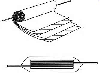
FIG. 20 Construction of film-foil capacitor
In order to attain a high capacitance value the dielectric film should be as thin as is practicable for the required working voltage. Both polystyrene and poly carbonate resin films are made in a similar manner; by 'casting' a thin layer of resin, in a liquid form, in solution in a solvent, on to a continuously moving metal strip, from which the thin film layer is peeled after the solvent has been dried off.
This allows the production of very thin films, but the presence of small imperfections, such as trapped gas bubbles, limits the possible voltage which can be applied between the foil layers. Where high voltage components are required, such solution cast film dielectrics may often be used in double layer form, since this greatly lessens the possibility of two weak spots coinciding at a particular point.
Polypropylene and polyester films are both made by bi-directional (biaxial) stretching of a relatively thick extruded film, which facilitates the production of very thin films, having a high mechanical and electrical strength, together with an almost complete freedom from pin-holes.
In particular, the very high electrical breakdown strength of the polyester films permits high capacitance, compact capacitors to be made at a relatively low cost, and these form the bulk of the commercially manufactured non-polar components for routine use, where special qualities are not required. They are available in the capacitance range 1000pF - 4.7|uF, at voltage ratings of 100 - 1000V. The dielectric loss factor of polyester film capacitors (the extent to which energy is lost during the charge-discharge process) is however, relatively high, so where low loss capacitors are needed, other dielectrics will be preferred.
For low frequency use, polypropylene or poly styrene dielectric capacitors allow the manufacture of very low loss components, but they are relatively bulky where high values of capacitance are desired.
Polystyrene film/foil capacitors are very widely used where high precision capacitors are needed, for timing or filter circuitry.
Because of the low softening point of the poly styrene film, the last stage of the manufacturing process is normally to fuse the finished capacitor, with its insert wire connections, into a solid, stable, block by heating the capacitor briefly in an oven, to give the type of structure shown in FIG. 21.
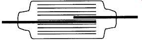
FIG. 21 Polystyrene-foil capacitor
However, the low melting point of this dielectric carries the penalty that, if a soldering iron is applied to the connecting wires for too long, or too close to the body of the capacitor, it may cause internal melting of the film, and lead to a short-circuited component.
Where low working voltages, up to, say, 60V, are adequate, very high capacitance values are possible, in compact forms, with poly carbonate film dielectrics.
Metallized film types
These have much the same physical form as film-foil capacitors, except that the continuous strip foil con ducting plates are replaced by thin conducting films of metal, vacuum evaporated on to the surface of the dielectric itself, as shown in FIG. 22a.
a. Single side metallization
b. Film metallization on both sides
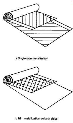
FIG. 22 Constructional methods of metallized film capacitors
This is then wound into a roll, as before, and metal is sprayed onto the ends of the cylinder, as shown, in section, in FIG. 23, to make an electrical contact with the conducting layers of metalizing.
This form of construction has the very great practical advantage that, if an electrical breakdown occurs in the film dielectric layer, this won’t destroy the capacitor, but will only burn of f a disc shaped area of the metalizing immediately surrounding the puncture, as shown in FIG. 24.
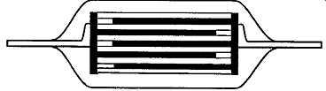
FIG. 23 Cross-section through wound metallized film capacitor
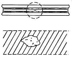
FIG. 24 Effect of self-heating of metallized film capacitor
Also, since the stored energy of the capacitor will be explosively released in such an action, the layer of metalizing will be removed very effectively from the immediate area of the breakdown. The penalty for this self-healing characteristic is that the loss factor of such components is higher than that of the film foil types, and the practicable precision of capacitance value is also much less good.
Such capacitors will generally have a 'tolerance' (a possible error) of capacitance value of+/- 20%. Two forms of metallized layer can be used in this type of construction: that in which two separate films are metallized, each with a plain strip along one edge, and wound together as shown in FIG. 22a, or that in which a single strip of film is metallized, on both sides, as shown in FIG. 22b, and then wound with a plain, un-metallized, strip of film as an interleaving layer.
This construction demands more skill in the original metalizing of the film, but offers the advantages of a higher capacitance per unit volume - because the two conducting layers are immediately in contact with the dielectric layer, without undesired air spaces - and a greater stability of capacitance during use.
Metallized paper, and metal foil/paper dielectric capacitors may still, occasionally, be found. Paper has quite good electrical properties, provided it’s dry.
However, preventing the long term ingress of moisture is difficult, even when the paper is impregnated with some water repellent material such as oil or wax.
Fortunately such components are now rarely en countered in electronics applications.
Stacked film/foil capacitors This style of manufacture, which is shown in FIG. 25, has come into greater use in recent years because it avoids, to a large extent, the inherent parasitic inductance of the wound film/foil or metallized film types.
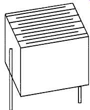
FIG. 25 Stacked film-foil capacitor
It is, understandably, more difficult in manufacture, but it lends itself more readily to the 'radial' style of lead formation, shown in FIG. 26a, which is more convenient for use in the 'population' of printed circuit boards (PCBs) than the 'axial' style of lead formation shown in FIG. 26b. Otherwise, the characteristics of the wound foil and stacked foil components are substantially identical.
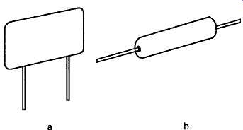
FIG. 26 Radial and axial lead configurations Mica dielectric capacitors
Mica is, in many ways, an almost ideal dielectric film, in that it can, with
care, be split into exceedingly thin, puncture free, layers. It has a dielectric
constant which is two or three times greater than that of the common plastics
films, it’s heat resistant, it has a high electrical strength, and a low dielectric
loss, which is maintained up to very high operating frequencies.
Unfortunately, it’s expensive, and, because it’s rigid, it can only be used in stacked layer constructions. It’s used, most commonly, for high power industrial applications, or for the manufacture of high precision, low loss, capacitors having capacitance values in the range 2.2 - 4700pF, at working voltages up to 1000V, for use in radio frequency, or high quality timer applications.
These capacitors usually have their conducting plates formed by opposed layers of silver, applied either chemically or as an electrically conductive paint, though metal foil electrodes are used in higher voltage or power rating components.
Ceramic capacitors Over the years a very wide range of electrical ceramics has been developed, ranging from relatively low dielectric constant, low loss, materials to those which can give dielectric constant (k) values up to 50,000, de pending on their precise composition and production and firing techniques.
These products are based on various mixes of titanium and zirconium dioxides, calcium, barium, strontium and magnesium titanates and zirconates, together with various 'rare earth' additions, the whole being tailored to give a wide range of dielectric proper ties.
Since there is, understandably, a degree of rivalry between manufacturers, many of their blends and process techniques are not disclosed, and many of their products are unique to themselves. This means that there is now little direct equivalence, except in the case of the more simple materials, or those ceramics made to meet a particular specification, between the pro ducts of one manufacturer and another.
Clearly, capacitors made from 'high-k' ceramics can allow high values of capacitance to be offered with units of very small physical size, having values up to, perhaps, 0.1uF in a pea-sized disc component, at a working voltage of 20-30V. The drawback with these very high-k materials is that their actual dielectric constant may be very strongly temperature dependent, as is also their dielectric loss.
However, where the actual value of the capacitance is relatively unimportant, provided that it’s adequate, as would be the case, for example, in RF by-pass applications, such ceramic disc components are widely used.
The lower k materials can offer quite good performance, with low dielectric loss values maintained up to very high frequencies, and reasonable precision of capacitance value. They find wide application in radio frequency (RF) use, in values ranging from 1pF - 2200pF, at 60 - 100V working ratings.
The actual dielectric materials used in ceramic capacitors are usually specified in relation to their temperature coefficient, and the nominal characteristics of the more common ones are shown in Table 3.
===
Table 3 Electrical properties of ceramics
Material Dielectric constant Temperature
('k') coefficient Alumina Titanium dioxide Magnesium silicate ('Steatite')
'???'
•N150'
•X7R*
'Z5U*
'N750' Barium titanate ('High-k') Barium titanate zirconate 8.1-9.5 70-90 5.5-7.0 20-30 50-200 75-150 100-500 100-500 1000-10,000 10,000-50,000 (ppmfiC)
-100
-150
-20 to -50
+/-30
-150
-270
-750
-75 0
-500 to-1000
>-1500
===
While the dielectric constant of most of the common ceramics has a negative temperature characteristic, there are some ceramic blends in which this has a small positive value. These are designated P30 or P100, referring to their temperature coefficient, and they are used for temperature compensation purposes in radio circuitry.
Capacitors are constructed from these ceramic materials in a variety of forms, of which the most common are the disc types shown in FIG. 27a, the concentric tube type of FIG. 27b, and the stacked multiple layer type shown in FIG. 27c. For this purpose, modern manufacturing techniques allow small rectangles of ceramic to be produced in thicknesses in the range 0.025 to 0.1mm, depending on the capacitance values and working voltages required.
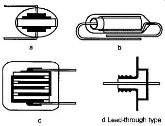
FIG. 27 Ceramic capacitor forms. Lead-through type.
Originally the conducting plates for these capacitors would be formed by firing on to the surface of the ceramic body a frit composed of glass and silver powders, but higher performance specifications now require platinum or palladium plate electrodes.
As in the case of the other types of fixed value capacitors, the complete unit will be sealed against ingress of moisture by dipping in a suitable synthetic resin encapsulant, although, sometimes, a fired ceramic coating is used.
To produce small, high capacitance value, low working voltage devices, particularly suited for supply line decoupling in computer logic applications, the 'barrier layer' construction is employed. In this technique, a disc of fired high-£ ceramic, such as barium titanate, is heated in a reducing atmosphere, so that it’s changed into an electrically conducting material.
The disc is then heated in air, to re-oxidize the surface layers to a depth of, say, 0.025mm, to give a very thin effective dielectric layer, and conducting metal electrodes are then applied.
Ceramic tube capacitors are widely employed as 'feed-through' decoupling elements, as shown in FIG. 27d.
Variable capacitors
It’s occasionally necessary to be able to vary the value of capacitance provided by the component, for example, in the adjustment of the 'tuning' of an inductor/capacitor tuned circuit. The two main classes of component used to provide this facility operate either by moving a pair of parallel plates into or out of mesh, so as to alter the effective area of the opposed conductors, or by altering the degree of compression in a stack X) f such plates.
Some of the common forms in which such variable value capacitors are made are shown in FIG. 28.
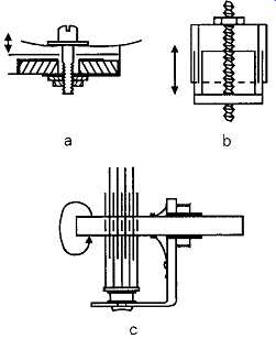
FIG. 28 Various forms of variable (trimmer) capacitor
The variable mesh parallel-plate air-spaced capacitors, generally called tuning capacitors, have the best electrical characteristics of this style of component, but they are bulky, and because of their physical size, suffer from a degree of parasitic inductance, simply due to the necessary length of the conducting path.
They can also be made in multiple ganged forms, as shown in FIG. 29, which allow electrically isolated capacitors to be simultaneously adjusted by a common shaft, and are commonly used in radio receivers for the parallel adjustment of multiple tuned circuits. They are available in up to four-ganged forms, but variable capacitors with more than two gangs are becoming scarce.
The relationship between the capacitance of a tuning capacitor, and the shaft rotational angle, is seldom linear, except in the case of the smaller 'trimmer' capacitors, since tuning capacitors will normally be intended to provide a linear change of frequency, as a function of shaft rotation.
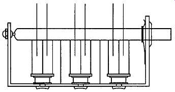
FIG. 29 Multiple ganged air-spaced capacitor
This will require a 'square-law' characteristic, be cause of the way in which the frequency is related to the inductance and capacitance of a tuned circuit, expressed in the equation
F = 1 / I2 pi _/LCC (4)
In the case of the tuning capacitors used in small portable radio sets, the gaps between the meshing plates of the tuning capacitor will frequently be filled with thin sheets of some plastics insulating material, in order to allow the spacing between the plates to be reduced, without the need for a high degree of mechanical precision in manufacture.
These solid dielectric variable capacitors are not suitable for precision purposes because small accidental movements of the plastics dielectric plates may introduce unwanted changes in capacitance, which are unrelated to the degree of shaft rotation.
'Compression trimmers', in which a stack of plates are pressed into greater proximity by a central adjusting screw, usually employ thin layers of a plastics film as a dielectric, although, in earlier times, the material employed was nearly always thin sheet mica.
Spurious effects
Although both resistors and capacitors suffer to some extent from the presence of unwanted characteristics, in the case of resistors the main problem is the presence of inductance, as noted above. However, this is usually swamped by the resistance of the component, and is of little practical effect except at very high frequencies, or with low resistance values, particularly since these will often be of wire wound types.
Capacitors, however, are the most complex of all the passive components, in respect of their underlying physical behavior, and differ considerably from the notional 'pure' capacitance which one might depict by the circuit symbol shown in FIG. 30a.
A broad distinction can be drawn between a polar, (i.e. electrolytic) and non-polar (i.e. film, mica, or ceramic dielectric) types, in terms of the equivalent circuit introduced by the component, but, in general, this will more nearly be of the form shown in FIG. 30b.
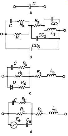
FIG. 30 Spurious components inherent in capacitors
In this, C is the effective capacitance of the unit, which will be somewhat dependent on the operating frequency, voltage and temperature. In series with this element of capacitance is a resistance Rk representing the dielectric loss factor, which is strongly dependent on temperature and operating frequency, and in parallel with C is the leakage resistance, Rl -- also very temperature dependent.
In all capacitors, there will be a series element of resistance Rs and a series inductance Ls simply due to the mechanical construction of the component, together with a small amount of distributed parasitic capacitance (CC1,CC2,CC3,) which can probably be ignored, except at radio frequencies, or in the construction of high purity LC oscillators.
In electrolytic types there will also be a unidirectional conductive path, D, in series with a further nonlinear resistance, R4, as shown in FIG. 30c, which comes into effect if the polarity is reversed, but can also have an effect under zero polarizing voltage conditions, where these have persisted for long enough to allow deterioration of the electrolytically formed dielectric layer.
The action of the polarizing voltage has a complex electrochemical/ionic effect, and, if reversed polarity conditions are allowed to arise, the nature of the dielectric layer will be modified in ways which will permanently affect the other characteristics of the component.
Although non-polar capacitors avoid some of the undesirable characteristics of the electrolytic types, they can suffer to a much greater extent from dielectric hysteresis and other stored charge effects of the ‘electret' type, represented in FIG. 30d by the generator Ee, and the series capacitor Ce
All of these spurious effects can generally be ignored in most normal applications, but it’s prudent to remember that the shortcomings of the capacitor in one's hand may sometimes give rise to unexpected effects, particularly when it’s used in some position where the performance of the component is crucial to the behavior of the circuit.
One must also remember that, for these reasons, the impedance of a practical capacitor does not decrease linearly with frequency, in the manner suggested by equation (4) above, but tends to follow the type of curve shown in FIG. 31, in which is shown the actual impedances offered by a 0.1uF polyester foil capacitor, and 1uF, 47uF and 4700uF aluminum electrolytic types.
The shape of these impedance curves also illustrates the reason why, if a low impedance is desired over a wide frequency range, it’s necessary to connect one or more small capacitors in parallel with any large value electrolytic, to avoid the increase in impedance at higher frequencies which will otherwise occur.
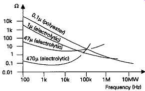
FIG. 31 Impedance of capacitors as a function of frequency