AMAZON multi-meters discounts AMAZON oscilloscope discounts
Aircraft electrical power can be derived from a variety of sources; these are categorized as either primary or secondary. Batteries are primary sources of electrical power found on most aircraft delivering direct current. (Secondary sources of power are described in Section 6.) There are several types of battery used on aircraft, defined by the types of materials used in their construction; these include lead-acid and nickel cadmium batteries. The choice of battery type depends mainly on performance and cost. Other types of battery are being considered for primary power on aircraft; these include lithium and nickel-metal hydride. Electrical power delivered by batteries is used for a variety of applications, e.g. lights, radios, instruments, and motors. This section reviews the battery types used on aircraft, typical applications and how they are installed and maintained.
1. Overview
The main aircraft battery is a primary source of electrical power; its use can be controlled by the pilot or by automatic means. The main battery provides autonomous starting for the engine(s) or auxiliary power unit (APU) when external ground power is not available. Typical current requirement during APU starting is 1000 A, albeit for a short period of time. Batteries also supply essential loads in the event of generator failure. It is an airworthiness requirement that the main battery(s) supplies essential services for a specified period of time. Other air craft systems are supplied with their own dedicated batteries, e.g. aircraft emergency lights. Individual computers use their own battery sources to provide non-volatile memory. Battery type and maintenance requirements have to be understood by the aircraft engineer to ensure safe and reliable operation and availability.
The battery is constructed from a number of individual cells; generic cell features consist of two electrodes (the anode and cathode) and electrolyte contained within a casing. Cell materials vary depending on the type of battery performance required for a given cost. The simple primary cell (FIG . 1) causes an electron flow from the cathode (negative) through the external load to the anode (positive). The materials used refer to the two types of battery cell in wide spread use on aircraft for the primary source of power: lead-acid or nickel-cadmium. These are maintained on the aircraft and treated as line-replaceable units; a full description of these two battery types is provided in this section. Cells used within other aircraft equipment or systems are typically made from lithium or nickel-metal hydride materials. These are not maintained as individual items on the aircraft, they are installed/removed as part of the equipment that they are fitted into; in this case only a brief description is provided.
===========
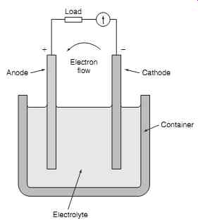
FIG. 1 Electrical storage cell
Cathode; Load; Container; Electrolyte; Anode; Electron flow
==========
Key point: The main aircraft battery is a primary source of electrical power; its use can be controlled by the pilot or by automatic means.
2. Storage cells
The basic function of any electrical cell is the conversion of chemical energy into electrical energy. The cells can be considered as a chemical means of storing electrical energy. Electrons are removed from the (positive) cathode and deposited on the (negative) anode.
The electrolyte is the physical means of migration between the cathode/anode. The attraction of electrons between cathode/anode creates a potential difference across the cell; the cathode/anode are attached to external terminals for connection to the equipment or system. Material types used for the cathode/anode and electrolyte will determine the cell voltage.
Key maintenance point: Different battery types possess different characteristics both in terms of what they are used for, and in terms of how they should be maintained; always refer to maintenance manual instructions for servicing.
Cells are categorized as either primary (where they can only be used once) or secondary (where they can be recharged). In the primary cell, the chemical activity occurs only once, i.e. during discharge. By applying current through a secondary cell in the opposite direction to that of discharging, the chemical reaction is reversed and the cell can be used again. The cathode/anode are returned to their original charged form; the cell therefore becomes a chemical means of storing electrical energy.
Key maintenance point: It can be dangerous to attempt charging a primary cell. In the secondary cell, the chemical activity is reversible.
The energy storage capacity of a cell is determined by the amount of material available for chemical reaction. To maximize the storage capacity, the physical areas of the cathode and anode are made as large as possible, normally by constructing them as plates.
Capacity is stated in ampere-hours; batteries are rated with low or high discharge rates, either 10 hours or 1 hour. The battery's capacity will gradually deteriorate over time depending on usage, in particular the charge and discharge rates. For aircraft maintenance purposes, we need to define the acceptable capacity of the main battery(s); this is the ratio of actual capacity and rated capacity, expressed as a percentage. Actual capacity must not fall below 80% of the rated capacity; therefore testing is required on a periodic basis.
Memory effect is observed in some secondary cells that cause them to hold less charge; cells gradually lose their maximum capacity if they are repeatedly recharged before being fully discharged. The net result is the cell appears to retain less charge than specified.
All secondary cells have a finite life and will gradually lose their capacity over time due to secondary chemical reactions; this occurs whether the cell is used or not. They also have a finite number of charge and discharge cycles since they lose a very small amount of storage capacity during each cycle.
Secondary cells can be damaged by repeated deep discharge or repeated over-charging.
Storage cells have internal resistance; this is usually very small but it has the effect of limiting the amount of current that the cell can supply and also reducing the amount of electromotive force (e.m.f.) available when connected to a load. Internal resistance varies significantly with the distance between plates.
For this reason, the gap is made as small as practicably possible. This internal resistance is sometimes shown as a series resistor within the cell for design purposes, but it is normally omitted in circuit diagrams used in maintenance and wiring diagram manuals. Internal resistance is affected by temperature and this leads to practical issues for certain cell types.
Test your understanding
Describe the process whereby secondary cells gradually lose their maximum capacity (memory effect).
A number of cells are linked together in series to form a battery. The total battery terminal voltage is the sum of individual cell voltages, see FIG. 2(a). In this illustration, six cells are connected in series to for a 12 V battery. The circuit symbols for individual cells and a battery are shown in FIG. 2(b). All of the individual cells are contained within a battery case, see FIG. 2(c).
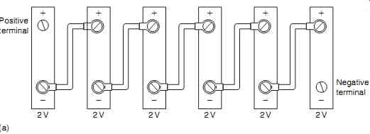
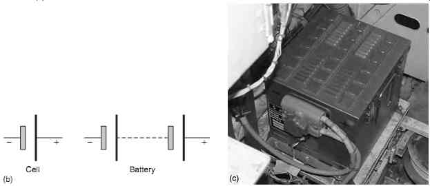
FIG. 2 Cells and batteries: (a) connection of cells to form a battery; (b)
symbols for cells and a battery; (c) typical battery casing
========
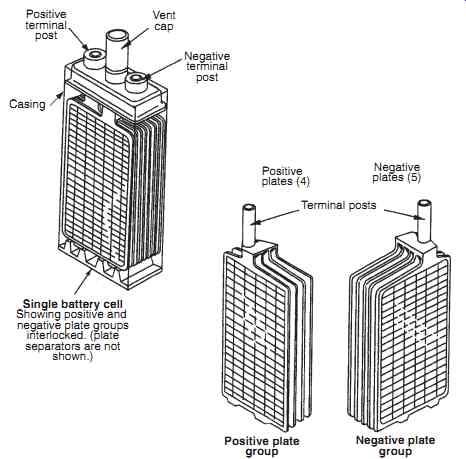
FIG. 3 Lead-acid cell construction
Positive terminal post; Single battery cell: Showing positive and negative plate groups interlocked. (plate separators are not shown.) Casing; Vent cap; Negative terminal post; Positive plates (4); Positive plate group; Negative plate group; Negative plates (5); Terminal posts
========
3. Lead-acid batteries
Developed in 1859, this is the oldest secondary cell technology in aircraft use today. Despite advances in alternative technologies, lead-acid batteries have retained market share (particularly in general aviation) due to the relatively low cost and mature technology.
This type of battery has widespread applications on general aviation fixed and rotary wing aircraft due to the high current available for engine start and relatively low manufacturing cost (compared with nickel cadmium batteries). The surface area of the plates, strength of the electrolyte and temperature determine the actual capacity of a lead-acid cell. There are two types of lead-acid battery used in aircraft: flooded (wet-cell) and sealed. The disadvantages of flooded batteries are that they require regular maintenance, they liberate gas during charging and the electrolyte can be spilt or leak. Spillage and/or leakage of the electrolyte requires immediate clean-up to avoid corrosion. These problems are overcome with sealed lead acid batteries. Although lead-acid batteries remain popular with GA aircraft, this battery technology will eventually be phased out due to environmental issues.
3.1 Construction
Flooded cells are housed within an impact- and acid resistant casing made from polystyrene-based materials. The casing retains the two terminals and includes a vent cap to prevent gas pressure build-up whilst not allowing the electrolyte to escape. A single battery cell contains a number of positive and negative plate groups constructed as illustrated in FIG. 3. The individual plates are separated by a porous material to prevent short circuit through physical contact; there is space below the plates to allow any material shed from the plates to accumulate without shorting the plates.
Flooded cells can be accessed on an individual basis for checking the content and condition of the electrolyte.
Key point: Since each positive plate is always positioned between two negative plates, there is actually one more negative plate than the positives.
Each positive plate is a cast lead/antimony frame formed as a grid; this is impregnated with a paste of lead dioxide (PbO 2 ). The negative plate is a similar frame containing lead (Pb); this is sometimes referred to as 'spongy lead '. In practice, a typical cell is constructed with several plates in order to get the required current output. Positive plates distort when chemical reactions take place on only one side; for this reason, there are always an even number of positive plates sandwiched between an odd number of negative plates.
All positive plates are connected together as are all the negatives. The plates are interlaced and separated by a porous separator that allows free circulation of the electrolyte at the plate surfaces; the plates are all stacked within the cell container. The electrolyte is sulphuric acid diluted with distilled (pure) water (H 2 SO 4 ).
Test your understanding
What are the advantages and disadvantages of flooded (wet-cell) batteries?
3.2 Charging/discharging
When fully charged, each cell has a potential difference of 2.5 V (falling to 2.2 V after a period of approximately one hour) at its terminals; when discharged, this potential difference is 1.8 V. A six-cell battery would produce 13.2 V fully charged, and 10.8 V DC when discharged. A twelve-cell battery would pro duce 26.4 V DC fully charged, and 21.6 V DC when discharged. During normal use of lead-acid cells, the terminal voltage stays at around 2 V for a long period of cell life, this is referred to as the cell's nominal voltage. When fully charged, the positive plate is lead dioxide (PbO2 ) and the negative plate is lead (Pb).
Connecting an external load to the battery completes the electrical circuit, electrons are transferred from the negative plate and the battery starts to discharge. The chemical reaction that takes place during discharge changes each of the plates into lead sulphate (PbSO4 ). Molecules of water are formed, thereby diluting the electrolyte. For a given battery capacity, a steady discharge rating forms part of the battery specification, e.g. a 20 hour rate produces a constant current for 20 hours until the cell is discharged.
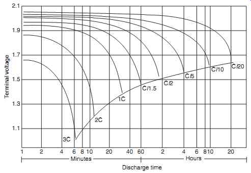
FIG. 4 Lead-acid cell discharge characteristics.
FIG. 4 illustrates typical lead-acid battery characteristics at different discharge currents. The discharge current, in amps (A), is expressed as a fraction of the numerical value of C. For example, 0.1 C means C/10 A, and discharging will take approximately 10 hours. If the battery capacity was 35 Ah, a discharge current of 3.5 A can be expressed as 0.1 C (or C/10). This means that batteries of different sizes can be compared by a single set of graphs. Since a battery may be rated for different discharge times, its rated capacity will normally be an indication of current used. With a 20-hour discharge capacity, the chart shows that C/20 will discharge the battery at 1 A cur rent in 20 hours.
The condition of each cell can be determined by the specific gravity (SG) of its electrolyte. When the battery is charged, the above process is reversed. The lead sulphate on the positive plate is returned to lead peroxide. The negative plate is returned to lead, and the electrolyte is restored to its original specific gravity; SG ranges will be from 1.25-1.3 (charged) down to 1.15-1.2 when discharged. Table 1 summarizes the chemical aspects of a charged and discharged lead-acid cell.
=======
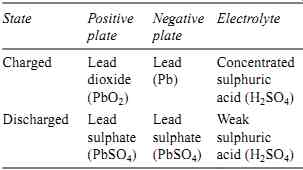
Table 1 Chemical aspects of a charged and discharged lead-acid cell.
State Positive plate
Negative plate
Electrolyte
Charged Lead dioxide (PbO2 )
Lead (Pb)
Concentrated sulphuric acid (H 2 SO 4 )
Discharged Lead sulphate (PbSO4 )
Lead sulphate (PbSO4 )
Weak sulphuric acid (H 2 SO 4 )
=======
3.3 Maintenance
Flooded lead-acid batteries are susceptible to dam age at low temperatures due to freezing of the electrolyte causing plate damage. The point at which the electrolyte freezes depends on its specific gravity; at a specific gravity of 1.15 (discharged) the freezing point is _ 15ºC. To prevent freezing, the specific gravity should be maintained at higher levels; at a specific gravity of 1.275 (charged) the freezing point is _ 62ºC. Although this guards against freezing, the consequence of maintaining a battery in this condition is that it will gradually self-discharge.
Lead-acid batteries require a three-month capacity check, and have approximately 18-24 months ' life.
The condition of a fully charged lead-acid battery can be confirmed by three factors:
-- The terminal voltage remains at its maximum level
-- There is a free discharge of gas
-- The SG is in the range 1.25-1.3.
The specific gravity of the electrolyte provides the definitive means of checking the charged condition of a lead-acid cell; this must be checked with a hydrometer on a periodic basis. (Specific gravity of a fluid is the relative density, or ratio of fluid's weight compared to pure water.) The electrolyte must always cover the plates; it can be topped up with distilled water. Differences of specific gravity readings between cells indicates that the battery is reaching the end of its useful life.
Key maintenance point: Specific gravity is temperature-dependent, and correction factors must be applied when taking measurements (refer to maintenance manual instructions).
Key maintenance point: When taking specific gravity readings from lead acid cells, the acid sample should always be returned into the same cell.
Charging of lead-acid batteries should be from a constant voltage source. Excessive charging rates can lead to boiling of the electrolyte; fumes containing droplets of electrolyte can escape the battery. These fumes can become noxious unless the battery is properly ventilated. The voltage per cell during charging should not exceed 2.35V. Sulphation occurs when an excess of lead sulphate builds up on the plates. This happens with a fully charged battery over a period of several weeks when the battery self-discharges. To prevent this, the battery should be re-charged in accordance with the maintenance manual instructions. Sulphation can eventually occur on a permanent basis and the sulphate will not go back into solution when charged. Over time, the lead sulphate gradually occupies more space on the plates thereby reducing capacity. This can be removed by drawing a heavy charge current causing particles to be removed from the plates and subsequently accumulated at the bottom of the cell. Eventually the plates become uneven in cross-section and distorted, leading to cracks being formed. Particles will accumulate at the bottom of the cell and this can lead to shorting of the plates. Sulphating is accelerated by small (trickle) discharging/charging together with incorrect electrolyte strength and levels.
In the event of electrolyte spillage/leaks, (always refer to the aircraft maintenance manual for any specific requirements) the following generic actions should be taken:
1. Report the incident.
2. Mop-up the electrolyte with a damp rag or sponge.
3. Brush the affected area with a dilute solution of sodium bicarbonate.
4. Sponge the area with clean water; dry thoroughly.
5. Press a moist piece of blue litmus paper on the affected area; a change of color to red indicates the presence of acid (repeat steps 3-4 until the acid is removed).
6. Leave for 24 hours, and then check for any evidence of corrosion.
7. Restore any protective finish to the aircraft structure.
3.4 Sealed batteries
Maintenance and servicing costs associated with flooded cells can be overcome with sealed lead-acid batteries. This technology was developed in the 1970s and has been in place since the 1980s and is known as valve-regulated lead-acid (VRLA); the sealed lead-acid ( SLA) effectively provides maintenance free lead-acid batteries.
Cell plates are made from lead calcium; the electrolyte is sulphuric acid diluted with distilled water. Plates are separated by an absorbent glass mat (AGM) that absorbs gasses liberated from the plates during charging. The lead plates are purer (99.99%) than flooded cell materials since they do not have to support their own weight. The electrolyte is absorbed between the plates and immobilized by a very fine fiberglass mat.
This glass mat absorbs and immobilizes the acid while keeping the electrolyte in contact with the plates. This allows a fast reaction between and electrolyte and plate material during charge/discharge. There is no disintegration of the active materials leading to a short-circuit.
Key maintenance point: It is not possible to check the SG of the electrolyte; the battery can only be checked by measuring the terminal voltage.
The internal resistance of sealed lead-acid cells is lower than flooded cells, they can handle higher temperatures, and self-discharge more slowly. They are also more tolerant to the attitude of the aircraft.
The product is inherently safer than the flooded cell due to reduced risk of spillage, leakage and gassing.
Maintenance requirements are for a capacity check only. The overall capacity-to-weight ratio of sealed lead-acid batteries is superior to flooded lead-acid batteries. Since they are sealed, they can be shipped as non-hazardous material via ground or air.