AMAZON multi-meters discounts AMAZON oscilloscope discounts
(cont. from part 1)
4. AC motors
AC motors offer significant advantages over their DC counterparts. AC motors can, in most cases, duplicate the operation of DC motors and they are significantly more reliable. The main reason for this is that the commutator arrangements (i.e. brushes and slip-rings) fitted to DC motors are inherently troublesome. Because the speed of an AC motor is determined by the frequency of the AC supply that is applied it, AC motors are well suited to constant speed applications.
AC motors are generally classified into two types:
-- synchronous motors
-- induction motors.
The synchronous motor is effectively an AC generator (i.e. an alternator) operated as a motor. In this machine, AC is applied to the stator and DC is applied to the rotor. The induction motor is different in that no source of AC or DC power is connected to the rotor. Of these two types of AC motor, the induction motor is by far the most commonly used.
Key point: The principle of all AC motors is based on the generation of a rotating magnetic field. It is this rotating field that causes the motor's rotor to turn.
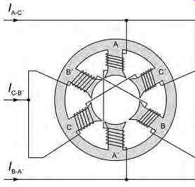
FIG. 33 Arrangement of the field windings of a three-phase AC motor
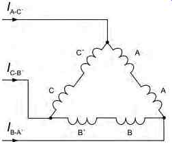
FIG. 34 AC motor as a delta-connected load
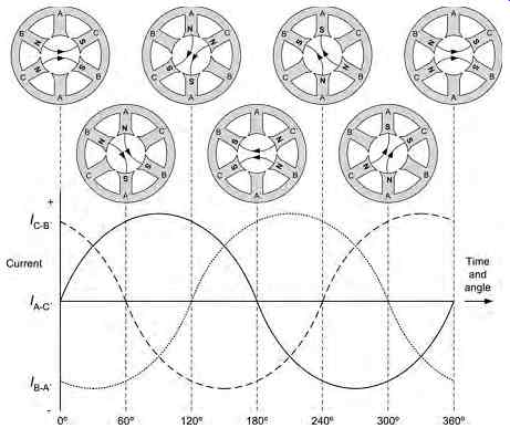
FIG. 35 AC waveforms and magnetic field direction
4.1 Producing a rotating magnetic field
Before we go any further it's important to understand how a rotating magnetic field is produced. Take a look at FIG. 33 which shows a three-phase stator to which three-phase AC is applied. The windings are connected in delta configuration, as shown in Fig. 34. It is important to note that the two windings for each phase (diametrically opposite to one another) are wound in the same direction.
At any instant the magnetic field generated by one particular phase depends on the current through that phase. If the current is zero, the magnetic field is zero. If the current is a maximum, the magnetic field is a maximum. Since the currents in the three windings are 120° out of phase, the magnetic fields generated will also be 120° out of phase.
The three magnetic fields that exist at any instant will combine to produce one field that acts on the rotor. The magnetic fields inside the motor will combine to produce a moving magnetic field and, at the end of one complete cycle of the applied current, the magnetic field will have shifted through 360° (or one complete revolution).
FIG. 35 shows the three current waveforms applied to the field system. These waveforms are 120° out of phase with each other. The waveforms can represent either the three alternating magnetic fields generated by the three phases, or the currents in the phases.
We can consider the direction of the magnetic field at regular intervals over a cycle of the applied current (i.e. every 60°). To make life simple we take the times at which one of the three current waveforms passes through zero (i.e. the point at which there will be no current and therefore no field produced by one pair of field windings). For the purpose of this exercise we will use the current applied to A and C ' as our reference waveform (i.e. this will be the waveform that starts at 0° on our graph).
At 0°, waveform C-B _ is positive and waveform B-A_ is negative. This means that the current flows in opposite directions through phases B and C, and so establishes the magnetic polarity of phases B and C. The polarity is shown in FIG. 35. Note that B _ is a north pole and B is a south pole, and that C is a north pole and C _ is a south pole.
Since at 0° there is no current flowing through phase A, its magnetic field is zero. The magnetic fields leaving poles B _ and C will move towards the nearest south poles C _ and B. Since the magnetic fields of B and C are equal in amplitude, the result ant magnetic field will lie between the two fields, and will have the direction shown.
At the next point, 60° later, the current wave forms to phases A and B are equal and opposite, and waveform C is zero. The resultant magnetic field has rotated through 60°. At point 120°, waveform B is zero and the resultant magnetic field has rotated through another 60°. From successive points (corresponding to one cycle of AC), you will note that the resultant magnetic field rotates through one revolution for every cycle of applied current. Hence, by applying a three-phase alternating current to the three windings we have been able to produce a rotating magnetic field.
Key point: If three windings are placed round a stator frame, and three-phase AC is applied to the windings, the magnetic fields generated in each of the three windings will combine into a magnetic field that rotates. At any given instance, these fields combine together in order to produce a resultant field that which acts on the rotor. The rotor turns because the magnetic field rotates.
4.2 Synchronous motors
We have already shown how a rotating magnetic field is produced when a three-phase alternating current is applied to the field coils of a stator arrangement. If the rotor winding is energized with DC, it will act like a bar magnet and it will rotate in sympathy with the rotating field. The speed of rotation of the magnetic field depends on the frequency of the three-phase AC supply and, provided that the supply frequency remains constant, the rotor will turn at a constant speed. Furthermore, the speed of rotation will remain constant regardless of the load applied. For many applications this is a desirable characteristic; however, one of the disadvantages of a synchronous motor is that it cannot be started from a standstill by simply applying three-phase AC to the stator. The reason for this is that the instant AC is applied to the stator, a high-speed rotating field appears. This rotating field moves past the rotor poles so quickly that the rotor does not have a chance to get started. Instead, it is repelled first in one direction and then in the other.
Another way of putting this is simply that a synchronous motor (in its pure form) has no starting torque.
Instead, it is usually started with the help of a small induction motor (or with windings equivalent to this incorporated in the synchronous motor). When the rotor has been brought near to synchronous speed by the starting device, the rotor is energized by connecting it to a DC voltage source. The rotor then falls into step with the rotating field. The requirement to have an external DC voltage source as well as the AC field excitation makes this type of motor somewhat unattractive!
Key point: The synchronous motor is so called because its rotor is synchronized with the rotating field set up by the stator. Its construction is essentially the same as that of a simple AC generator (alternator).
Key point: Synchronous motors are not self-starting and must be brought up to near synchronous speed before they can continue rotating by themselves. In effect, the rotor becomes 'frozen ' by virtue of its inability to respond to the changing field!
4.3 Three-phase induction motors
The induction motor derives its name from the fact that AC currents are induced in the rotor circuit by the rotating magnetic field in the stator. The stator construction of the induction motor and of the synchronous motor are almost identical, but their rotors are completely different.
The induction motor rotor is a laminated cylinder with slots in its surface. The windings in these slots are one of two types. The most common uses so called squirrel cage construction (see FIG. 36) that is made up of heavy copper bars connected together at either end by a metal ring made of copper or brass.
No insulation is required between the core and the bars because of the very low voltages generated in the rotor bars. The air gap between the rotor and stator is kept very small so as to obtain maximum field strength.
The other type of winding contains coils placed in the rotor slots. The rotor is then called a wound rotor. Just as the rotor usually has more than one conductor, the stator usually has more than one pair of poles per coil, as shown in FIG. 37.
Key point: The induction motor is the most commonly used AC motor because of its simplicity, its robust construction and its relatively low cost. These advantages arise from the fact that the rotor of an induction motor is a self-contained component that is not actually electrically connected to an external source of voltage.
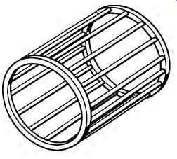
FIG. 36 Squirrel cage rotor construction.
Regardless of whether a squirrel cage or wound rotor is used, the basic principle of operation of an induction motor is the same. The rotating magnetic field generated in the stator induces an e.m.f. in the rotor. The current in the rotor circuit caused by this induced e.m.f. sets up a magnetic field. The two fields interact, and cause the rotor to turn. FIG. 38 shows how the rotor moves in the same direction as the rotating magnetic flux generated by the stator.
From Lenz's law we know that an induced current opposes the changing field which induces it. In the case of an induction motor, the changing field is the rotating stator field and so the force exerted on the rotor (caused by the interaction between the rotor and the stator fields) attempts to cancel out the continuous motion of the stator field.
Hence the rotor will move in the same direction as the stator field and will attempt to align with it. In practice, it gets as close to the moving stator field but never quite aligns perfectly with it !
Key point: The induction motor has the same stator as the synchronous motor. The rotor is different in that it does not require an external source of power.
Current is induced in the rotor by the action of the rotating field cutting through the rotor conductors.
This rotor current generates a magnetic field which interacts with the stator field, resulting in a torque being exerted on the rotor and causing it to rotate.
4.4 Slip, torque and speed
We have already said that the rotor of an induction motor is unable to turn in sympathy with the rotating field and, in practice, a small difference always exists.
In fact, if the speeds were exactly the same, no relative motion would exist between the two, and so no e.m.f. would be induced in the rotor. For this reason the rotor operates at a lower speed than that of the rotating magnetic field. This phenomenon is known as slip and it becomes more significant as the rotor develops increased torque, as shown in FIG. 39.
From FIG. 39, for a torque of A the rotor speed will be represented by the distance AC whilst the slip …will be represented by distance AD. Now:
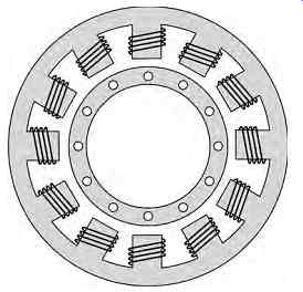
FIG. 37 Typical stator construction
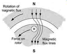
FIG. 38 Force on the rotor of an
induction motor
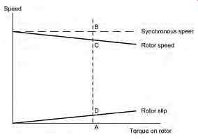
FIG. 39 Relationship between torque and slip
For values of torque within the working range of the motor (i.e. over the linear range of the graph shown in FIG. 39 ), the slip directly proportional to the torque and the per-unit slip is given by: Per-unit slip slip synchronous speed AD AB __
Now since AD _ A B _ BC, slip (synchronous speed) (rotor speed) __
thus:
Per-unit slip (synchronous speed) (rotor speed) synchronous s speed AB BC AB _ _
The percentage slip is given by: Percentage slip (synchronous speed) (rotor speed) synchronous speed AB BC AB 100% __ _ _ 100%
The actual value of slip tends to vary from about 6% for a small motor to around 2% for a large machine. Hence, for most purposes the induction motor can be considered to provide a constant speed (determined by the frequency of the current applied to its stator); however, one of its principal disadvantages is the fact that it is not easy to vary the speed of such a motor!
Note that, in general, it is not easy to control the speed of an AC motor unless a variable frequency AC supply is available. The speed of a motor with a wound rotor can be controlled by varying the current induced in the rotor but such an arrangement is not very practical as some means of making contact with the rotor windings is required. For this reason, DC motors are usually preferred in applications where the speed must be varied. However, where it is essential to be able to adjust the speed of an AC motor, the motor is invariably powered by an inverter. This consists of an electronic switching unit which produces a high-current three-phase pulse-width-modulated (PWM ) output voltage from a DC supply, as shown in FIG. 40
Key point
The rotor of an induction motor rotates at less than synchronous speed, in order that the rotating field can cut through the rotor conductors and induce a current flow in them. This percentage difference between the synchronous speed and the rotor speed is known as slip. Slip varies very little with normal load changes, and the induction motor is therefore considered to be a constant-speed motor.
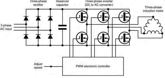
FIG. 40 Using an inverter to produce a variable output speed from an
AC induction motor
Example
An induction motor has a synchronous speed of 3600 r.p.m. and its actual speed of rotation is measured as 3450 r.p.m. Determine (a) the per-unit slip and (b) the percentage slip.
(a) The per-unit slip is found from: Per-unit slip 3,600 3,450 3,600 150 3,600 _ _ __ 0 042.
(b) The percentage slip is given by: Percentage slip 3,600 3,450 3,450 150 3,450 100% %
Inside an induction motor, the speed of the rotating flux, N, is given by the relationship: N f p _
where N is the speed of the flux (in revolutions per second), f is the frequency of the applied AC (Hz)
and p is the number of pole pairs.
Now the per-unit slip, s, is given by: s NN N _ _ _ _ AB BC AB r
where N is the speed of the flux (in revolutions per second) and Nr is the rotor speed.
Now: sN N N __ r
from which: NNsNNs r () __ _ _ 1
and:
where Nr is the speed of the rotor (in revolutions per second), f is the frequency of the applied AC (Hz) and s is the per-unit slip.
Example 6
An induction motor has four poles and is operated from a 400 Hz AC supply. If the motor operates with a slip of 2.5% determine the speed of the output rotor.
Thus the rotor has a speed of 195 revolutions per second (or 11,700 r.p.m.).
Example 7
An induction motor has four poles and is operated from a 60 Hz AC supply. If the rotor speed is 1700 r.p.m. determine the percentage slip.
Now: N f p s r () __ 1
Expressed as a percentage, this is 5.6%
4.5 Single- and two-phase induction motors
In the case of a two-phase induction motor, two windings are placed at right angles to each other.
By exciting these windings with current which is 90º out of phase, a rotating magnetic field can be created.
A single-phase induction motor, on the other hand, has only one phase. This type of motor is extensively used in applications which require small low-output motors. The advantage gained by using single-phase motors is that in small sizes they are less expensive to manufacture than other types. Also they eliminate the need for a three-phase supply. Single-phase motors are used in communication equipment, fans, portable power tools, etc. Since the field due to the single phase AC voltage applied to the stator winding is pulsating, single-phase AC induction motors develop a pulsating torque. They are therefore less efficient than three-phase or two-phase motors, in which the torque is more uniform.
Single-phase induction motors have only one stator winding. This winding generates a field which can be said to alternate along the axis of the single winding, rather than to rotate. Series motors, on the other hand, resemble DC machines in that they have commutators and brushes.
When the rotor is stationary, the expanding and collapsing stator field induces currents in the rotor which generate a rotor field. The opposition of these fields exerts a force on the rotor, which tries to turn it 180° degrees from its position. However, this force is exerted through the center of the rotor and the rotor will not turn unless a force is applied in order to assist it. Hence some means of starting is required for all single-phase induction motors.
Key point: Induction motors are available that are designed for three-phase, two-phase and single-phase operation.
The three-phase stator is exactly the same as the three-phase stator of the synchronous motor. The two-phase stator generates a rotating field by having two windings positioned at right angles to each other. If the voltages applied to the two windings are 90 ° out of phase, a rotating field will be generated.
Key point: A synchronous motor uses a single- or three-phase stator to generate a rotating magnetic field, and an electromagnetic rotor that is supplied with DC. The rotor acts like a magnet and is attracted by the rotating stator field. This attraction will exert a torque on the rotor and cause it to rotate with the field.
Key point: A single-phase induction motor has only one stator winding; therefore the magnetic field generated does not rotate. A single-phase induction motor with only one winding cannot start rotating by itself.
Once the rotor is started rotating, however, it will continue to rotate and come up to speed. A field is set up in the rotating rotor that is 90° out of phase with the stator field. These two fields together pro duce a rotating field that keeps the rotor in motion.
4.6 Capacitor starting
In an induction motor designed for capacitor starting, the stator consists of the main winding together with a starting winding which is connected in parallel with the main winding and spaced at right angles to it. A phase difference between the current in the two windings is obtained by connecting a capacitor in series with the auxiliary winding. A switch is included solely for the purposes of applying current to the auxiliary winding in order to start the rotor (see FIG. 41).
On starting, the switch is closed, placing the capacitor in series with the auxiliary winding. The capacitor is of such a value that the auxiliary winding is effectively a resistive-capacitive circuit in which the current leads the line voltage by approximately 45°.
The main winding has enough inductance to cause the current to lag the line voltage by approximately 45°.
The two field currents are therefore approximately 90° out of phase. Consequently the fields generated are also at an angle of 90°. The result is a revolving field that is sufficient to start the rotor turning.
After a brief period (when the motor is running at a speed which is close to its normal speed) the switch opens and breaks the current flowing in the auxiliary winding. At this point, the motor runs as an ordinary single-phase induction motor. However, since the two-phase induction motor is more efficient than a single-phase motor, it can be desirable to maintain the current in the auxiliary winding so that motor runs as a two-phase induction motor.
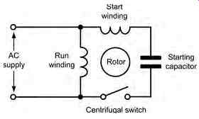
FIG. 41 Capacitor starting arrangement
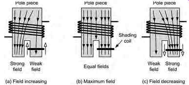
FIG. 42 Action of a shaded pole
In some types of motor a more complicated arrangement is used with more than one capacitor switched into the auxiliary circuit. For example, a large value of capacitor could be used in order to ensure sufficient torque for starting a heavy load and then, once the motor has reached its operating speed, the capacitor value can be reduced in order to reduce the current in the auxiliary winding. A motor that employs such an arrangement, where two different capacitors are used (one for starting and one for running) is often referred to as capacitor-start, capacitor-run induction motor. Finally, note that, since phase shift can also be produced by an inductor, it is possible to use an inductor instead of a capacitor. Capacitors tend to be less expensive and more compact than comparable inductors and therefore are more frequently used.
Since the current and voltage in an inductor are also 90 ° out of phase, inductor starting is also possible. Once again, a starting winding is added to the stator. If this starting winding is placed in series with an inductor across the same supply as the running winding, the current in the starting winding will be out of phase with the current in the running winding.
A rotating magnetic field will therefore be generated, and the rotor will rotate.
Key point
In order to make a single-phase motor self starting, a starting winding is added to the stator.
If this starting winding is placed in series with a capacitor across the same supply as the running winding, the current in the starting winding will be out of phase with the current in the running winding.
A rotating magnetic field will therefore be generated, and the rotor will rotate. Once the rotor comes up to speed, the current in the auxiliary winding can he switched-out, and the motor will continue running as a single-phase motor.
4.7 Shaded pole motors
A different method of starting a single-phase induction motor is based on a shaded-pole. In this type of motor, a moving magnetic field is produced by constructing the stator in a particular way. The motor has projecting pole pieces just like DC machines; and part of the pole surface is surrounded by a copper strap or shading coil.
As the magnetic field in the core builds, the field flows effortlessly through the unshaded segment. This field is coupled into the shading coil which effectively constitutes a short-circuited loop. A large cur rent momentarily flows in this loop and an opposing field is generated as a consequence. The result is simply that the unshaded segment initially experiences a larger magnetic field than does the shaded segment.
At some later time, the fields in the two segments become equal. Later still, as the magnetic field in the unshaded segment declines, the field in the shaded segment strengthens. This is illustrated in FIG. 42
Key point: In the shaded pole induction motor, a section of each pole face in the stator is shorted out by a metal strap. This has the effect of moving the magnetic field back and forth across the pole face. The moving magnetic field has the same effect as a rotating field, and the motor is self-starting when switched on.
Test your understanding
1. Explain the difference between synchronous AC motors and induction motors.
2. Explain the main disadvantage of the synchronous motor.
3. An induction motor has a synchronous speed of 7200 r.p.m. and its actual speed of rotation is measured as 7000 r.p.m. Determine (a) the per-unit slip and (b) the percentage slip.
4. An induction motor has four poles and is operated from a 400 Hz AC supply. If the motor operates with a slip of 1.8% determine the speed of the output rotor.
5. An induction motor has four poles and is operated from a 60 Hz AC supply. If the rotor speed is 1675 r.p.m. determine the percentage slip.
6. Explain why a single-phase induction motor requires a means of starting.
5. Practical aircraft generating systems
Generators are a primary source of power in an air craft and can either produce direct or alternating cur rent (DC or AC) as required. They are driven by a belt drive (in smaller aircraft), or engine/APU accessory gearbox in larger aircraft. Generators will have sufficient output to supply all specified loads and charge the battery(s). Most avionic equipment requires a regulated and stable power supply depending on its function, e.g. in the case of lighting, it would be inconvenient if the intensity of lighting varied with engine speed. Generator output is affected by internal heat and this has to be dissipated. Cooling methods can include natural radiation from the casing, however this is inadequate for high-output devices where ram-air is directed from a scoop and directed into the generator's brush-gear and commutator. In some installations, e.g. helicopters, a fan is installed to provide cooling when the aircraft is hovering. We know from basic theory that a generator's output will vary depending on the input shaft speed. A means of regulating the generator's output to the bus is required as is a means of overload protection.
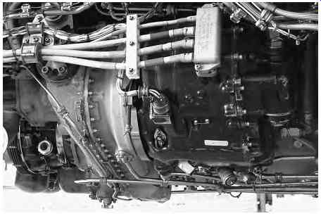
FIG. 43 Main three-phase AC generator mounted in the engine compartment of a large passenger aircraft.
5.1 DC generators
DC generators are less common on modern aircraft due to their low power-to-weight ratio, poor performance at low r.p.m. and high servicing costs. The latter is due to the need for inspection and servicing of brushes and commutators since they have irregular surfaces/contact area and conduct the entire load cur rent. Carbon brushes are porous and will absorb sub stances including moisture; this provides an amount of inherent lubrication. At altitude, the atmosphere is dryer and this leads to higher brush wear. Without any lubrication, arcing occurs and static charges build up; brush erosion is accelerated. Additives can be incorporated into the brushes that deposit a lubricating film on the commutator; this needs time to build up a sufficient protection; brushes need to be run in for several hours before the protective layer forms (this is often mistaken for contamination). The alternative is an in-built lubrication that is consumed as part of the natural brush wear, i.e. no film is deposited.
Key maintenance point
Automotive style alternators are normally installed on general aviation and light aircraft to overcome the shortfalls of DC generators. Larger aircraft use brushless AC generators.
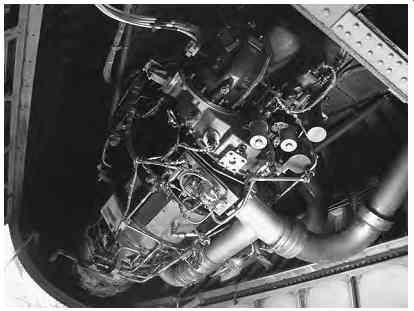
FIG. 44 Tail-mounted auxiliary power unit (APU) with three-phase AC generator
(top of picture)
FIG. 45 Overhead electrical panel fitted with main and APU generator indicators and displays. This panel provides the crew with an instant overview of the status of the electrical generating system and the AC and DC distribution buses)
5.2 Alternators
Automotive style alternators comprise a rotor, stator and rectifier pack. The rotor contains the field coil arranged in six sections around the shaft. Each section forms a pole piece that is supplied via slip-rings and brushes. The alternator has no residual magnetism, its field has to be excited by a DC supply (e.g. the battery). When energized, the rotor's pole pieces
produce north and south poles. As these poles are rotated they induce currents in the stator windings; these are wound at 120° and this produces three phase AC. The AC output is fed to a diode rectifier pack comprising six high-current diodes, see Fig. 46 which produces a DC output. This has to be regulated before connecting to the various aircraft systems. Voltage regulators used with alternators on general aviation aircraft can be electromechanical or electronic. There are two types of electromechanical regulators: sensing coil with contacts and carbon-pile.
Modern solid-state electronic regulators are more reliable as they use no mechanical parts.
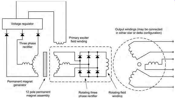
FIG. 46 A practical brushless AC generator arrangement.
The alternators previously described rely on slip rings and brushes, albeit with reduced current loading. Slip-rings and brushes require maintenance in the workshop thereby incurring an associated cost burden.
The brushless generator is a more complex device but has significantly increased reliability coupled with reduced maintenance requirements. A schematic diagram for the brushless generator is shown in FIG. 46 ; the device can be divided into three main sections:
-- permanent magnet generator
-- rotating field
-- three-phase output.
The AC generator uses a brushless arrangement based on a rotating rectifier and permanent magnet generator ( PMG ). The output of the PMG rectifier is fed to the voltage regulator which provides current for the primary exciter field winding. The primary exciter field induces current into a three-phase rotor winding.
The output of this winding is fed to the shaft-mounted rectifier diodes which produce a pulsating DC output which is fed to the rotating field winding. It is important to note that the excitation system is an integral part of the rotor and that there is no direct electrical connection between the stator and rotor.
The output of the main three-phase generator is supplied via current transformers (one for each phase) that monitor the load current in each line. An additional current transformer can also be present in the neutral line to detect an out-of-balance condition (when the load is unbalanced an appreciable current will flow in the generator's neutral connection).
The generator output is fed to the various aircraft systems and a solid-state regulator. This rectifies the output and sends a regulated direct current to the stator exciter field of the PMG. The regulator maintains the output of the generator at 115 V AC and is normally contained within a generator control unit (GCU ); this is unit is further described in Section 7.
Although the regulator controls the output voltage of the generator, its frequency will vary depending on the speed of shaft rotation. Variable frequency power supplies (sometimes called frequency wild) are accept able for resistive loads, e.g. de-icing, but they are not suitable for many induction motor loads that need to run at constant speed, e.g. fuel pumps and gyroscopic instruments. Furthermore, certain loads are designed for optimum efficiency at the specified frequency of 400 Hz, e.g. cooling fans. Some larger multi-engine aircraft operate the generators in parallel; it is essential that each generator is operating at the same frequency.
Constant frequency can be achieved in one of two ways: controlling the shaft speed by electromechanical methods using a constant speed drive ( CSD ) or by controlling the generator output frequency electronically (variable speed constant frequency : VSCF).
Key point: A three-phase AC generator can be made brush less by incorporating an integral excitation system in which the field current is derived from a rotor-mounted rectifier arrangement. In this type of generator the coupling is entirely magnetic and no brushes and slip-rings are required.
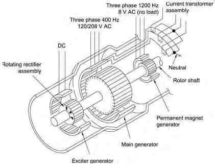
FIG. 47 Layout of a typical brushless AC generator
5.3 Constant speed drive/integrated drive generator
The CSD is an electromechanical device installed on each engine. The input shaft is connected to the engine gearbox; the output shaft is connected to the generator.
The CSD is based on a variable ratio drive employing a series of hydraulic pumps and differential gears. CSDs can be disconnected from the engine via a clutch, either manually or automatically. Note that it is only possible to reconnect the clutch on the ground. Modern commercial aircraft employ a combined CSD and brushless AC generator, in one item - the integrated drive generator (IDG). Typical characteristics are a variable input speed of 4500/9000 r.p.m. and a constant output speed of 12,000 _ 150 r.p.m. The IDG on a large commercial aircraft is oil-cooled and produces a 115/200 V 400 Hz three-phase, 90 m kVA output.
5.4 Variable speed constant frequency (VSCF)
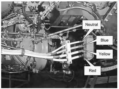
FIG. 48 Typical
main generator showing three-phase output cabling
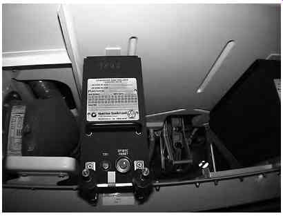
FIG. 49 Typical generator
control unit (GCU)
Both the constant speed drive and integrated drive generator are complex and very expensive electromechanical devices. Advances in semiconductor technology has facilitated the development of solid-state products that can convert variable frequencies into 115/200 V AC, 400 Hz three-phase power supplies.
Variable speed constant frequency (VSCF) systems comprise a generator and power converter.
A brushless AC generator is mounted onto the engine accessory gearbox as before; its output voltage and frequency varies in accordance with engine speed. The gearbox increases the generator speed by a ratio of 1:3, producing a variable output frequency between 1300 and 2500 r.p.m. The three-phase output of VSCF is full-wave rectified to produce a 270 V DC output. This direct current output is smoothed by large capacitors, filtered and fed into an inverter that produces a square wave output. The inverter converts the DC level into a three phase, pulse-width-modulated waveform. This is then converted in the sinusoidal output voltage. These outputs are then converted into AC through electronic circuits. The final output stage is monitored by a current transformer and electro magnetic interference filter ( CT / EMI ). Within the generator control unit (GCU ) a generator control relay (GCR ) energizes the field. This circuit can be interrupted by the pilot or automatically under fault conditions.
The VSCF generator conversion control unit (GCCU ) can either be integrated with the generator as a single engine mounted device (weighing typically 65 kg) or it can be located in the airframe. The latter arrangement has the advantage of making the engine accessories smaller; this means a lower profile nacelle In addition, the electronics can be located in a zone with reduced temperature and vibration.
VSCF systems are more reliable compared with constant speed drive and integrated drive generators since there are fewer moving parts. The VSCF system's moving parts consist of the generator's rotor and an oil pump used for cooling. The VSCF can be used for both primary and secondary power supplies; out puts of 110 kVA are achievable. Enabling technology for VSCF are the power transistors and diodes capable of handling currents in excess of 500 A. These diodes and transistors form the core of the rectifier and con version circuits of the GCCU. The VSCF contains an oil pump mounted on the generator shaft that circulates oil through the system; this oil is passed through a heat exchanger. Oil temperatures and pressures are closely monitored; warnings are given to the crew in the event of malfunctions. Oil level can be checked during ground servicing through a sight glass.
6. QUIZ: Multiple choice questions
1. The slip-rings in an AC generator provide a means of:
(a) connecting an external circuit to a rotating armature winding
(b) supporting a rotating armature without the need for bearings
(c) periodically reversing the current produced by an armature winding.
2. Decreasing the current in the field coil of a DC generator will:
(a) decrease the output voltage
(b) increase the output voltage
(c) increase the output frequency.
3. The rotor of an AC induction motor consists of:
(a) a laminated iron core inside a ' squirrel cage ' made from copper or aluminum
(b) a series of coil windings on a laminated iron core with connections via slip-rings
(c) a single copper loop which rotates inside the field created by a permanent magnet.
4. The slip speed of an AC induction motor is the difference between:
(a) the synchronous speed and the rotor speed
(b) the frequency of the supply and the rotor speed
(c) the maximum speed and the minimum speed
5. When compared with three-phase induction motors, single-phase induction motors:
(a) are not inherently ' self starting '
(b) have more complicated stator windings
(c) are significantly more efficient.
6. A three-phase induction motor has three pairs of poles and is operated from a 60 Hz supply.
Which one of the following gives the motor's synchronous speed?
(a) 1200 r.p.m.
(b) 1800 r.p.m.
(c) 3600 r.p.m.
7. In a star-connected three-phase system, the line voltage is found to be 200 V. Which one of the following gives the approximate value of phase voltage?
(a) 67 V
(b) 115 V
(c) 346 V
8. A single-phase AC generator has twelve poles and it runs at 600 r.p.m. Which one of the following gives the output frequency of the generator?
(a) 50 Hz
(b) 60 Hz
(c) 120 Hz.
9. In a balanced star-connected three-phase system the line current is 2 A and the line voltage is 200 V. If the power factor is 0.75 which one of the following gives the total power in the load?
(a) 300 W
(b) 520 W
(c) 900 W
10. The commutator in a DC generator is used to:
(a) provide a means of connecting an external field current supply
(b) periodically reverse the connections to the rotating coil winding
(c) disconnect the coil winding when the induced current reaches a maximum value.
11. The brushes fitted to a DC motor/generator should have:
(a) low coefficient of friction and low contact resistance
(b) high coefficient of friction and low contact resistance
(c) low coefficient of friction and high content resistance.
12. Self-excited generators derive their field current from:
(a) the current produced by the armature
(b) a separate field current supply
(c) an external power source.
13. In a shunt-wound generator:
(a) none of the armature current flows through the field
(b) some of the armature current flows through the field
(c) all of the armature current flows through the field
14. When combined with a CSD, a brushless three phase AC generator is often referred to as:
(a) a compound generator
(b) a ' frequency wild ' generator
(c) an IDG
15. An out-of-balance condition in an AC three phase system can be detected by means of:
(a) voltage sensors connected across each output line
(b) a dedicated field coil monitoring circuit
(c) a current transformer connected in the neutral line