AMAZON multi-meters discounts AMAZON oscilloscope discounts
Used in conjunction with an aircraft battery, engine driven generators are a primary source of electrical power in an aircraft. Generators can supply either direct or alternating current (DC or AC), as appropriate to the needs of an individual aircraft type. Motors (which can also be either DC or AC types) are fitted in aircraft in order to satisfy a wide range of needs.
Generators and motors share many similarities and this section provides an introduction to their operating principles by looking in more detail at the construction and operation of these indispensable aircraft electrical components. The section also includes a brief introduction to three-phase AC supplies, including the theoretical and practical aspects of their generation and distribution.
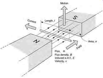
FIG. 1 A conductor moving inside a magnetic field
1. Generator and motor principles
In Section 1 we introduced the concept of electro magnetic induction. Put simply, this is the generation of an e.m.f. across the ends of a conductor when it passes through a change in magnetic flux. In a similar fashion, an e.m.f. will appear across the ends of a conductor if it remains stationary whilst the field moves. In either case, the action of cutting through the lines of magnetic flux results in a generated e.m.f. - see FIG. 1. The amount of e.m.f., e, induced in the conductor will be directly proportional to:
-- the density of the magnetic flux, B, measured in tesla (T)
-- the effective length of the conductor, l, within the magnetic flux
-- the speed, v, at which the lines of flux cut through the conductor measured in meters per second (m/s)
-- the sine of the angle, ?, between the conductor and the lines of flux.
The induced e.m.f. is given by the formula:
eBlv _ sin ?
Note that if the conductor moves at right angles to the field (as shown in FIG. 1) maximum e.m.f. will be induced. Conversely, if the conductor moves along the lines of flux (instead of at right angles) the induced e.m.f. will be zero.
Electricity and magnetism often work together to produce motion. In an electric motor, current flowing in a conductor placed inside a magnetic field produces motion. A generator, on the other hand, produces a voltage when a conductor is moved inside a magnetic field. These two effects are, as you might suspect, closely related to one another and they are vitally important in the context of aircraft electrical systems!
Key point: An e.m.f. will be induced across the ends of a conductor when there is relative motion between it and a magnetic field. The induced voltage will take its greatest value when moving at right angles to the magnetic field lines and its least value (i.e. zero) when moving along the direction of the field lines.
1.1 A simple AC generator
Being able to generate a voltage by moving a conductor through a magnetic field is extremely useful as it provides us with an easy way of generating electricity. Unfortunately, moving a wire at a constant linear velocity through a uniform magnetic field presents us with a practical problem simply because the mechanical power that can be derived from an aircraft engine is available in rotary (rather than linear) form!
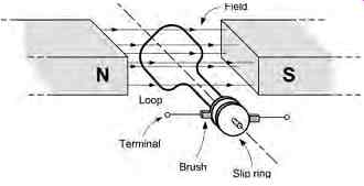
The solution to this problem is that of using the rotary power available from the engine (via a suitable gearbox and transmission) to rotate a conductor shaped into the form of loop as shown in FIG. 2. The loop is made to rotate inside a permanent magnetic field with opposite poles (N and S) on either side of the loop.
There now remains the problem of making contact with the loop as it rotates inside the magnetic field but this can be overcome by means of a pair of car bon brushes and copper slip-rings. The brushes are spring loaded and held against the rotating slip-rings so that, at any time, there is a path for current to flow from the loop to the load to which it is connected.
The opposite sides of the loop consist of conductors that move through the field. At 0° (with the loop vertical as shown at A in FIG. 4) the opposite sides of the loop will be moving in the same direction as the lines of flux. At that instant, the angle, ?, at which the field is cut is 0° and since the sine of 0° is 0 the generated voltage (from E _ Blv sin ? ) will consequently also be zero.
If the loop has rotated to a position which is 90° (position B in FIG. 4) the two conductors will effectively be moving at right angles to the field. At that instant, the generated e.m.f. will take a maximum value (since the sine of 90° is 1).
At 180° from the starting position the generated e.m.f. will have fallen back to zero since, once again, the conductors are moving along the flux lines (but in the direction opposite to that at 0 °, as shown in C of FIG. 4 ).
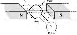
FIG. 2 A loop rotating within a magnetic field
At 270° the conductors will once again be moving in a direction which is perpendicular to the flux lines (but in the direction opposite to that at 90°). At this point (D of FIG. 4 ), a maximum generated e.m.f. will once again be produced. It is, however, important to note that the e.m.f. generated at this instant will be of opposite polarity to that which was generated at 90°.The reason for this is simply that the relative direction of motion (between the conductors and flux lines) has effectively been reversed.
Since E _ Blv sin ?, the e.m.f. generated by the arrangement shown in FIG. 4 will take a sinusoidal form, as shown in FIG. Note that the maximum values of e.m.f. occur at 90° and 270° and that the generated voltage is zero at 0°, 180° and 360°.
In practice, the single loop shown in FIG. 2 would comprise a coil of wire wound on a suitable non magnetic former. This coil of wire effectively increases the length of the conductor within the magnetic field and the generated e.m.f. will then be directly proportional to the number of turns on the coil.
Key point: In a simple AC generator a loop of wire rotates inside the magnetic field produced by two opposite magnetic poles. Contact is made to the loop as it rotates by means of slip-rings and brushes.
1.2 DC generators
When connected to a load, the simple generator shown in FIG. 3 produces a sinusoidal alternating current (AC) output. In many applications a steady direct current (DC) output may be preferred.
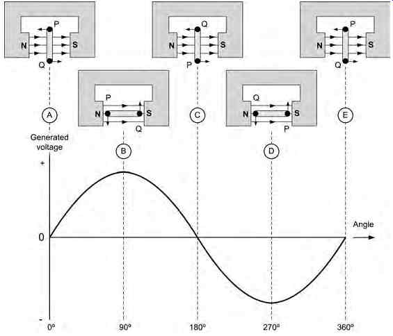
FIG. 4 E.m.f. generated at various angles
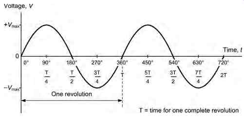
FIG. 5 Sinusoidal voltage produced by the rotating loop.
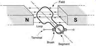
This can be achieved by modifying the arrangement shown in FIG. 3, replacing the brushes and slip rings with a commutator arrangement, as shown in FIG. 6. The commutator arrangement functions as a rotating reversing switch which ensures that the e.m.f. generated by the loop is reversed after rotating through 180°. The generated e.m.f. for this arrangement is shown in FIG. 7. It's worth comparing this waveform with that shown in FIG. 5 -you should be able to spot the difference immediately!
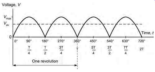
FIG. 7 E.m.f. generated (compare with FIG. 5 )
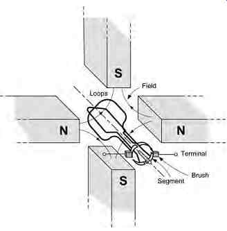
FIG. 8 An improved DC generator
The generated e.m.f. shown in FIG. 7, whilst unipolar (i.e. having only one polarity, either all positive or all negative), is clearly far from ideal since a DC power source should provide a constant voltage output rather than a series of pulses. One way of overcoming this problem is with the use of a second loop (or coil) at right angles to the first, as shown in FIG. 8. The commutator is then divided into four (rather than two) segments and the generated e.m.f. produced by this arrangement is shown in FIG. 9.
In real generators, a coil comprising a large number of turns of copper wire replaces the single-turn rotating loop. This arrangement effectively increases the total length of the conductor within the magnetic field and, as a result, also increases the generated output voltage. The output voltage also depends on the density of the magnetic flux through which the current carrying conductor passes. The denser the field the greater the output voltage will be.
Key point: A simple DC generator uses an arrangement similar to that used for an AC generator but with the slip-rings and brushes replaced by a commutator that reverses the current produced by the generator every 180 degrees.
1.3 DC generators
A simple DC motor consists of a very similar arrangement to that of the DC generator that we met earlier.
A loop of wire that is free to rotate is placed inside a permanent magnetic field (see FIG. 10 ). When a DC current is applied to the loop of wire, two equal and opposite forces are set up which act on the conductor in the directions indicated in FIG. 10.
The direction of the forces acting on each arm of the conductor can be established by again using the right-hand grip rule and Fleming's left-hand rule.
Now because the conductors are equidistant from their pivot point and the forces acting on them are equal and opposite, then they form a couple. The moment of this couple is equal to the magnitude of a single force multiplied by the distance between them and this moment is known as torque, T. Now, TFd _
... where T is the torque (in newton-meters, Nm), F is the force (N) and d is the distance (m).
We already know that the magnitude of the force F is given by F _ BIl, therefore the torque produced by the current-carrying thus the torque expression can be written:
TBIld _
where T is the torque (Nm), B is the flux density (T), I is the current (A), l is the length of conductor in the magnetic field (m), and d is the distance (m).
The torque produces a turning moment such that the coil or loop rotates within the magnetic field. This rotation continues for as long as a current is applied.
A more practical form of DC motor consists of a rectangular coil of wire (instead of a single turn loop of wire) mounted on a former and free to rotate about a shaft in a permanent magnetic field, as shown.
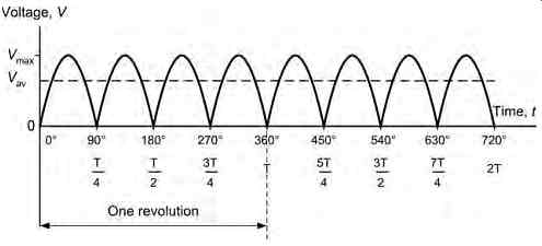
FIG. 9 E.m.f. generated (compare with FIG. 7) FIG. 10 Torque on a current-carrying
loop suspended within a permanent magnetic field.
In real motors, this rotating coil is know as the armature and consists of many hundreds of turns of conducting wire. This arrangement is needed in order to maximize the force imposed on the conductor by introducing the longest possible conductor into the magnetic field. Also, from the relationship F _ BIl it can be seen that the force used to provide the torque in a motor is directly proportional to the size of the magnetic flux, B. Instead of using a permanent magnet to produce this flux, in a real motor, an electro magnet is used. Here an electromagnetic field is set up using the solenoid principle ( FIG. 12). A long length of conductor is wound into a coil consisting of many turns and a current passed through it. This arrangement constitutes a field winding and each of the turns in the field winding assists each of the other turns in order to produce a strong magnetic field, as shown in FIG. 12
As in the case of the DC generator, this field may be intensified by inserting a ferromagnetic core inside the coil. Once the current is applied to the conducting coil, the core is magnetized and all the time the current is on it acts in combination with the coil to produce a permanent magnet, having its own N-S poles.
Now returning to the simple motor illustrated in FIG. 11, we know that when current is supplied to the rotating armature (rotor) a torque is produced.
In order to produce continuous rotary motion, this torque (turning moment) must always act in the same direction.
Therefore, the current in each of the armature conductors must be reversed as the conductor passes between the north and south magnetic field poles.
The commutator acts like a rotating switch, reversing the current in each armature conductor at the appropriate time to achieve this continuous rotary motion.
Without the presence of a commutator in a DC motor, only a half turn of movement is possible!
In FIG. 13(a) the rotation of the armature conductor is given by Fleming's left-hand rule (see Fig. 14). When the coil reaches a position mid-way way between the poles ( FIG. 13(b)), no rotational torque is produced in the coil. At this stage the commutator reverses the current in the coil. Finally ( FIG. 13(c)) with the current reversed, the motor torque now continues to rotate the coil in its original direction.
Key point: The torque produced by a DC motor is directly proportional to the product of the current flowing in the rotating armature winding.
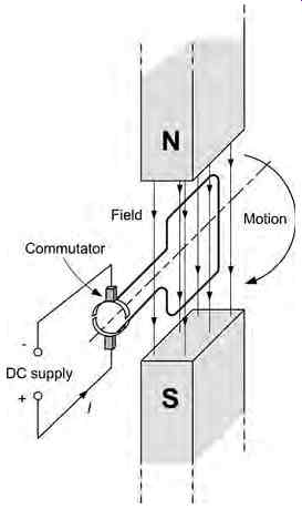
FIG. 11 Simple electric motor with commutator
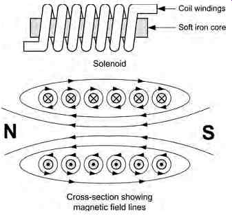
FIG. 12 Magnetic field produced by a solenoid
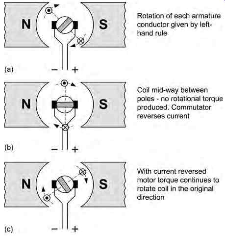
FIG. 13 Action of the commutator
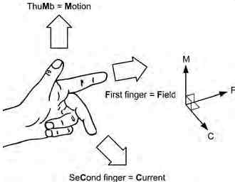
FIG. 14 Fleming's left-hand rule
FIG. 15 ). This arrangement results in a DC motor
1.4 Field connections
The field winding of a DC motor can be connected in various different ways according to the application envisaged for the motor in question. The following configurations are possible:
-- series-wound
-- shunt-wound
-- compound-wound (where both series and shunt windings are present)
In the series-wound DC motor the field winding is connected in series with the armature and the full armature current flows through the field winding (see that produces a large starting torque at slow speeds.
This type of motor is ideal for applications where a heavy load is applied from rest. The disadvantage of this type of motor is that on light loads the motor speed may become excessively high. For this reason this type of motor should not be used in situations where the load may be accidentally removed. A typical set of torque and speed characteristics for a series wound DC motor is shown in FIG.
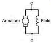
In the shunt-wound DC motor the field winding is connected in parallel with the armature and thus the supply current is divided between the armature and the field winding (see FIG. 17). This arrangement results in a DC motor that runs at a reasonably constant speed over a wide variation of load but does not perform well when heavily loaded. A typical set of torque and speed characteristics for a shunt-wound DC motor is shown.
FIG. 16 Typical torque and speed characteristic for a series-wound DC motor
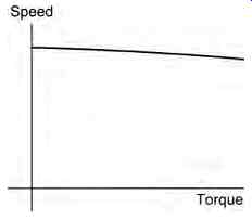
FIG. 18 Typical torque and speed characteristic for a shunt-wound DC
motor
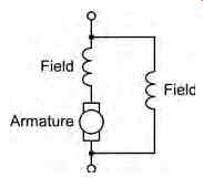
FIG. 19 Compound-wound DC motor
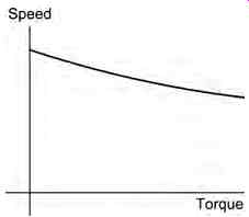
FIG. 20 Typical torque and speed characteristic for a compound-wound
DC motor
The compound-wound DC motor has both series and shunt field windings (see FIG. 19) and is there fore able to combine some of the advantages of each type of motor. A typical set of torque and speed characteristics for a compound-wound DC motor is shown in FIG.
Key point
In order to avoid the need for a large permanent magnet in a DC machine (i.e. a motor or generator), a separate field winding is used. This winding is energized with direct current. In the case of a DC generator, this current can be derived from the output of the generator (in which case it is referred to as self-excited generator) or it can be energized from a separate DC supply.
Key point
There is no real difference between the construction of a DC generator and that of a DC motor. The only significant distinction is that in a generator rotational mechanical energy is being converted to electrical energy whilst in the case of a motor the converse applies.
Key point
The output of a generator can be regulated by con trolling the intensity of its field: increasing the field current will produce a corresponding increase in output voltage whereas reducing the field current will produce a corresponding reduction in output.
1.5 Starter-generators
Some small aircraft starter generators eliminate the need for separate engine starter motors and DC generators. They usually have separate field windings (one for the starter motor and one for the generator) together with a common armature winding. When used for starting, the starter-generator is connected as a series-wound DC motor capable of producing a very high starting torque. However, when used as a generator the connections are changed so that the unit operates as shunt-wound generator producing reason ably constant current over a wide range of speed.
In the start condition, the low-resistance starter field and common armature windings of the starter generator are connected in series across the DC sup ply via a set of contactors. This arrangement ensures that a torque is produced that is sufficient to start an aircraft's turbine engine.
When the engine reaches self-sustaining speed, the current is broken through the first set of contactors and a second set of contactors operate, removing the external DC power supply from the starter generator and reconnecting the arrangement so that the generated the armature voltage is fed to the higher-resistance shunt field and the aircraft's main voltage regulator.
The advantage of this arrangement is not only that the starter-generator replaces two individual machines (i.e. a starter and a generator) with consequent savings in size and weight, but additionally that only a single mechanical drive is required between the engine and the starter-generator unit. The disadvantage of this arrangement is that the generator output is difficult to maintain at low engine r.p.m. and therefore starter generators are mainly found on turbine-powered air craft that maintain a relatively high engine r.p.m.
Test your understanding
1. In relation to a simple DC machine, explain the meaning of each of the following terms:
(a) slip-rings
(b) brushes
(c) field winding.
2. Explain the advantages and disadvantages of series-wound DC motors compared with shunt wound DC motors.
2. AC generators
AC generators, or alternators, are based on the principles that relate to the simple AC generator that we met earlier in Section 1.1. However, in a practical AC generator the magnetic field is rotated rather than the conductors from which the output is taken.
Furthermore, the magnetic field is usually produced by a rotating electromagnet (the rotor) rather than a permanent magnet. There are a number of reasons for this including:
(a) the conductors are generally lighter in weight than the magnetic field system and are thus more easily rotated
(b) the conductors are more easily insulated if they are stationary
(c) the currents which are required to produce the rotating magnetic field are very much smaller than those which are produced by the conductors.
Hence the slip-rings are smaller and more reliable.
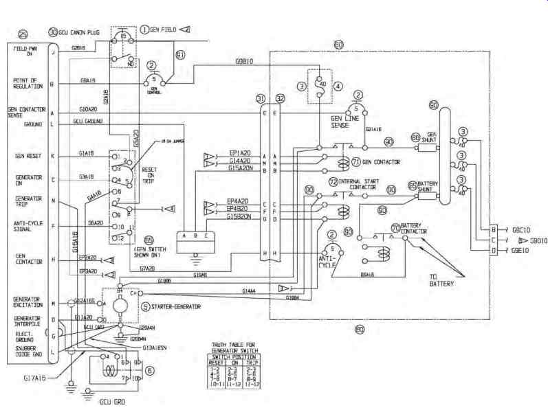
FIG. 21 Starter-generator circuit showing changeover contactors
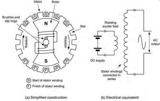
FIG. 22 Simplified construction of a single-phase AC generator
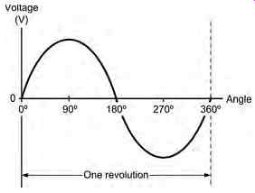
FIG. 23 Output voltage produced by the single-phase AC generator shown
in FIG. 22
FIG. 22 shows the simplified construction of a single-phase AC generator. The stator consists of
five coils of insulated heavy gauge wire located in slots in the high-permeability laminated core. These coils are connected in series to make a single stator winding from which the output voltage is derived.
The two-pole rotor comprises a field winding that is connected to a DC field supply via a set of slip rings and brushes. As the rotor moves through one complete revolution the output voltage will complete one full cycle of a sine wave, as shown in FIG. 23.
By adding more pairs of poles to the arrangement shown in FIG. 22 it is possible to produce several cycles of output voltage for one single revolution of the rotor. The frequency of the output voltage produced by an AC generator is given by: f pN _ 60 ...
...where f is the frequency of the induced e.m.f. (in Hz), p is the number of pole pairs, and N is the rotational speed (in rev/min).
Example 1:
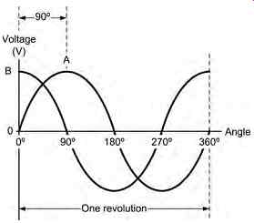
FIG. 25 Output voltage produced by the two-phase AC generator
shown in FIG. 24 FIG. 24 Simplified construction of a two phase AC generator
A 4-pole machine has 2 pairs of poles, thus p _ 2 and:
Key point: In a practical AC generator, the magnetic field excitation is produced by the moving rotor whilst the conductors from which the output is taken are stationary and form part of the stator.
2.1 Two-phase AC generators
By adding a second stator winding to the single-phase AC generator shown in FIG. 22, we can produce an alternator that produces two separate output voltages which will differ in phase by 90°. This arrangement is known as a two-phase AC generator.
When compared with a single-phase AC generator of similar size, a two-phase AC generator can produce more power. The reason for this is attributable to the fact that the two-phase AC generator will produce two positive and two negative pulses per cycle whereas the single-phase generator will only produce one positive and one negative pulse. Thus, over a period of time, a multi-phase supply will transmit a more evenly distributed power and this, in turn, results in a higher overall efficiency.
Key point: Three-phase AC generators are more efficient and produce more constant output than comparable single-phase AC generators.
2.2 Three-phase AC generators
The three-phase AC generator has three individual stator windings, as shown in FIG. 26. The output voltages produced by the three-phase AC generator are spaced by 120° as shown in FIG. 27. Each phase can be used independently to supply a different load or the generator outputs can be used with a three phase distribution system like those described in the next section. In a practical three-phase system the three output voltages are identified by the colors red, yellow, and blue or by letters A, B, and C respectively.
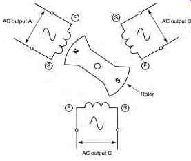
FIG. 26 Simplified construction of a three-phase AC generator
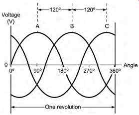
FIG. 27 Output voltage produced by the three-phase AC generator shown
in FIG. 26
3. Three-phase generation and distribution
When three-phase supplies are distributed there are two basic methods of connection:
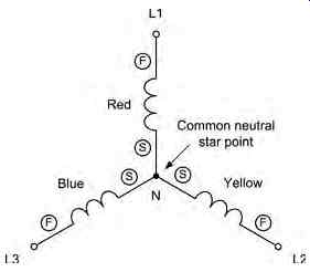
-- star (as shown in FIG. 28 )
-- delta (as shown in FIG. 29 )
A complete star-connected three-phase distribution system is shown in FIG. 30. This shows a three-phase AC generator connected a three-phase load. Ideally, the load will be balanced in which case all three load resistances (or impedances) will be identical.
The relationship between the line and phase voltages shown in FIG. 30 can be determined from the phasor diagram shown in FIG. 31. This diagram shows the relative directions of the three alternating phase voltages ( VP ) and the voltages between the lines ( VL ). From this diagram it is important to note that three line voltages are 120° apart and that the line voltages lead the phase voltages by 30°. In order to obtain the relationship between the line volt age, VL, and the phase voltage, VP, we need to resolve any one of the triangles, from which we find that:
Test your understanding
An alternator uses a 12-pole rotor and is to operate at a frequency of 400 Hz. At what speed must it be driven?
An alternator is to produce an output at a frequency of 60 Hz. If it uses a 4-pole rotor, determine the shaft speed at which it must be driven.
Re-arranging f pN _ 60
to make N the subject gives: N f p
Now cos30 3 2
and hence: VV LP __ 2
from which: VV LP _ 3
Note also that the phase current is the same as the line current, hence:
II PL _
An alternative, delta-connected three-phase distribution system is shown in FIG. 32. Once again this shows a three-phase AC generator connected a three-phase load. Here again, the load will ideally be balanced in which case all three load resistances (or impedances) will be identical.
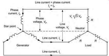
FIG. 30 A complete star-connected three-phase distribution system
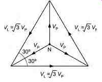
FIG. 31 Phasor diagram for the three phase star-connected system
In this arrangement the three line currents are 120° apart and that the line currents lag the phase currents by 30°. Using a similar phasor diagram to that which we used earlier, we can show that:
II LP _ 3
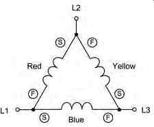
It should also be obvious that: VV PL _
Example 2
In a star-connected three-phase system the phase voltage is 105 V. Determine the line voltage.
VV LP V ___ _ 3 3 115 199 2.
Example 3
In a delta-connected three-phase system the line cur rent is 6 A. Determine the phase current.
3.1 Power in a three-phase system
In an unbalanced three-phase system the total power will be the sum of the individual phase powers.
Hence:
However, in the balanced condition the power is simply: PVI _ 3 cos PP f
where VP and IP are the phase voltage and phase current respectively and f is the phase angle.
Using the relationships that we derived earlier, we can show that, for both the star and delta-connected systems the total power is given by:
Example 4
In a three-phase system the line voltage is 110 V and the line current is 12 A. If the power factor is 0.8 determine the total power supplied.
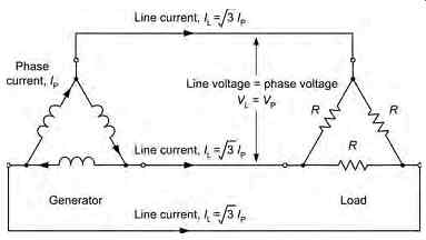
FIG. 32 A complete delta-connected three-phase distribution system.
Key point: The total power in a three-phase system is the sum of the power present in each of the three phases.
Test your understanding
1. The phase voltage in a star-connected AC system is 220 V. What will the line voltage be?
2. The phase current in a delta-connected system is 12 A. What will the line current be?
3. A three-phase system delivers power to a load consisting of three 12 Ohm resistors.
If a current of 8A is supplied to each load, determine the total power supplied by the system.
4. In a three-phase system the line voltage is 105 V and the line current is 8A. If the power factor is 0.75 determine the total power supplied.
