AMAZON multi-meters discounts AMAZON oscilloscope discounts
Many processes are required throughout the aircraft's operating life to ensure that it complies with the applicable airworthiness requirements and can be safely operated. The generic term for this range of processes is continuing airworthiness. The term 'maintenance' is used for any combination of overhaul, repair, inspection, replacement, modification or defect rectification of an aircraft or component, with the exception of the pre-flight inspection. Persons responsible for the release of an aircraft or a component after maintenance are the certifying staff. Maintenance of an aircraft and its associated systems requires a variety of test equipment and documentation; these are required by certifying staff to fulfill their obligations in ensuring continued airworthiness. Aircraft wiring cannot be considered as 'fit and forget'. Legislation is being proposed to introduce a new term: electrical wire interconnection system (EWIS); this will acknowledge the fact that wiring is just one of many components installed on the aircraft. EWIS relates to any wire, wiring device, or combination of these, including termination devices, installed in the air craft for transmitting electrical energy between two or more termination points. This section reviews some practical installation requirements, documentation and test equipment required by the avionics engineer to ensure the continued airworthiness of aircraft electrical and electronic systems.
1. Wire and cable installation
The importance of aircraft wire and cable selection, installation and maintenance cannot be overstated.
Modern aircraft (or upgraded older aircraft) are installed with more wiring, carrying more current than earlier generations of aircraft; much of this wiring carries digital signals. Wiring and cables must be treated as integral components of the aircraft; they are not to be treated as 'fit and forget'. Wires are formed from a single solid conductor or stranded conductors, contained within insulation and protective sheath materials. Cables can be defined as:
-- two or more separate wires within the same insulation and protective sheath
-- two or more wires twisted together
-- any number of wires covered by a metallic braid, or sheath
-- a single insulated conductor covered by a metallic outer conductor (co-axial cable)
The terms wires and cables are often interchanged. In this section, reference will be made to 'wiring' in the all-embracing generic sense; cables will be referred to in specific terms as and when required. Surveys and inspections of aircraft have revealed a number of issues and problems that require the close attention of system design and maintenance to ensure continuing airworthiness. Wire insulation can deteriorate over time (typically over ten years); exposed conductors create the environment for potential faults, spurious signals and arcing.
Wires are vulnerable to their installed environment, e.g. changes in temperature, exposure to moisture and vibration that can lead to open circuits and/or chafing. In certain areas of the aircraft, e.g. the leading/trailing edges of the wing and wheel wells, the physical environment is harsher than protected areas, e.g. the flight compartment or passenger cabin. The installation of wire and cable is very important; the following must be avoided:
-- sharp bend radii
-- unsupported wires
-- routing high and low power circuits in the same bundle, or loom
All the above can intensify the ageing and environ mental effects on wiring. Certain older standards of wire insulation, notably single-walled aromatic polyamide, have a known vulnerability to high temperature that can lead to the insulation forming small cracks; this can lead to moisture ingress, and overheating.
Under these conditions, the carbonized insulation becomes a conductor and the situation propagates leading to the possibility of fire. It is essential that older standards of wiring are inspected in accordance with maintenance schedule; the wiring should be replaced if there are any signs of deterioration. Care must be taken not to disturb or damage wiring during maintenance or inspection of nearby equipment.
Key maintenance point
Faulty wiring is often overlooked as the reason for systems becoming unserviceable. Line replaceable units (LRU) are often changed first, with the inevitable 'no fault found'.
1.1 Cable and wire looms
Grouping individual wires and cables into bundles forms a loom (or harness); these bundles are tied, or strapped together to form a secure assembly. Wire looms must be installed and maintained to ensure maximum integrity. The loom should be formed without twisting or overlapping the cables/wires. They can be tied together with waxed string, lacing cord or nylon straps.
These ties are made at regular intervals, equally spaced along the loom; the loom is then secured to the airframe with clamps. The current-carrying capacity of wires reduces in looms since the inner wires are not able to radiate heat efficiently. To illustrate this point, a single 20-gauge wire in free circulating air is rated at 14 A; this reduces depending on the number of wires in the loom:
-- single wire, 14 A
-- three wires, 9 A
-- seven wires, 7 A
-- twelve wires, 5 A
FIG. 1 provides some examples of installed wire looms. The loom will follow a path through the air craft dictated by existing structure and obstacles; additional support and protection is provided where required. Any bends or branches in the loom must not be so sharp that the loom becomes kinked (never bend or form wires or cables with pliers or any sharp edge). Looms must be installed such that they are supported with clamps and protected from chaffing through con tact with sharp edges, pipes and other wiring.
Cable clamps and grommets are used throughout the aircraft to provide this protection. General guide lines for the installation of wire looms are as follows:
-- Install with a downward slope away from equipment to prevent moisture running into the equipment
-- Do not install below fuel pipes
-- Avoid areas of high temperature
-- Install to minimize EMI
-- Make provision for at least one remake of the wire
-- Take care not to crush coaxial cables
-- Areas of high vibration require additional loom support
-- Breakout should not cross over the main loom
Open looms are formed with bound wires in a bundle; these are supported by p-clips and protected by grommets. The use of open looms is dictated by temperature and length of loom, together with any EMI considerations. Conduits ( FIG. 2) are used in specific areas, e.g. wing leading edges to protect wiring loom from rain and other fluids; these conduits are made from plastic or metal.
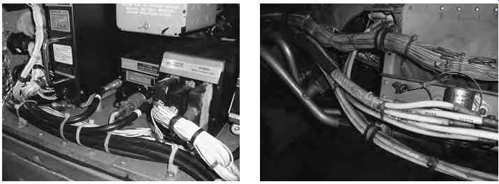
FIG. 1 Examples of installed wire looms
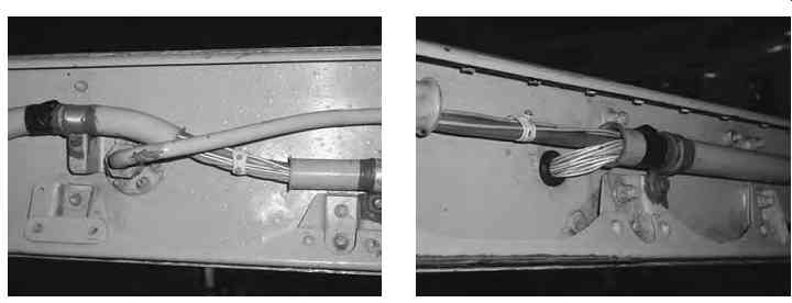
FIG. 2 Examples of cable-loom conduit
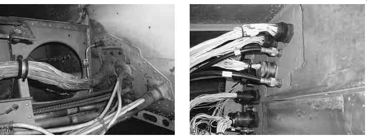
FIG. 3 Bulkhead wire looms: (a) sealant/potting, (b) connectors
When looms can be passed through bulkheads, they must be prevented from chaffing; this can be achieved by clamping or potting, see FIG. 3. Ducted looms are formed in channels made from a suitable material, e.g. aluminum alloy or composite. They provide more support and are used to guide the looms through and around specific areas of the aircraft. When the loom passes through bulkheads, they are often sealed with a rubber bung, see FIG. 3.
Certain areas of the aircraft will experience high vibration ( FIG. 4); wiring in these areas will be subjected to a harsher environment. These areas include:
-- wheels wells
-- empennage
-- wing roots
-- wing trailing edges
-- wing leading edges
-- engine pylons and nacelles
The wiring in these areas will be exposed to severe wind and moisture problems (SWAMP); wiring specifications and inspection requirements must be adhered to.
Key maintenance point
Cracking and breakdown of the insulation material through exposure to moisture, the speed of break down depending on both temperature and stress; this phenomenon is known as hydrolysis.
=======
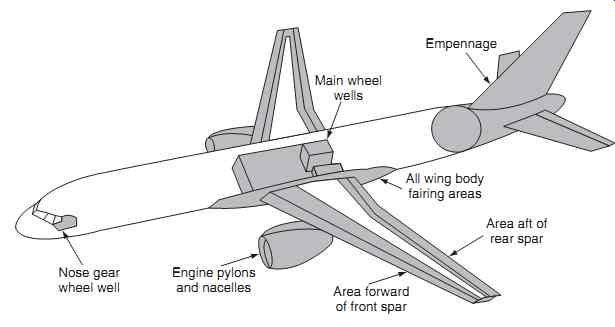
FIG. 4 High vibration areas
Main wheel wells Empennage All wing body fairing areas Area aft of rear spar Engine pylons and nacelles Area forward of front spar Nose gear wheel well
=======
Key maintenance point
Carbon arc tracking occurs when contaminating moisture (including aircraft fluids) creates a short circuit between an exposed conductor and the air craft structure or an adjacent exposed conductor at a different potential; this phenomenon is known as wet arc tracking.
Key maintenance point
Carbon arc tracking occurs in dry conditions when one or more conductors are shorted as a result of abrasion from: the aircraft structure, wire to wire, or installation error. This phenomenon is known dry arc tracking.
1.2 Wire terminations and connections
It is highly unlikely that a single wire or cable will be routed from the power source directly to the load -- it will invariably pass through bulkheads via connectors.
Certain areas in the aircraft are not suitable for the routing of wires (e.g. zones exposed to high tempera ture or EMI). Wiring is invariably installed in sections and joined at intervals. Terminations and connection types used will depend on a number of factors driven by cost and continued airworthiness requirements. The size and configuration of the aircraft will determine where connectors are needed and located. Other considerations are when aircraft sections (wings, fuselage, etc.) are manufactured at various geographical locations and come together at a different place for final assembly. Finally, the need for inspection, removal and installation of equipment needs to be considered; quick-release connectors are used for most line replaceable units (LRU), see FIG. 5.
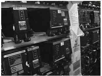
FIG. 5 Quick-release connectors (LRU)
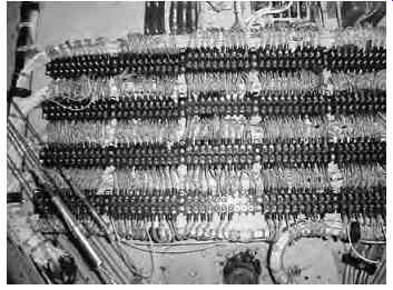
FIG. 6 Terminal blocks with connections
Wires can be joined by soldering, although this is normally only used within equipment. (Soldering aircraft wires reduces their flexibility and can lead to premature failure.) The majority of cable and wire terminations in the airframe are made by attaching crimp tags for use with terminal blocks or pin and sockets within connectors, see FIG. 6. There are two types of crimp: dimple and confined; the latter is the type normally used on aircraft.
The confined crimp is formed by compressing the crimp's shank onto the conductor. This results in the cold flow of metal between shank and conductor forming a homogeneous mass. The crimping operation also causes the crimp to form over the insulating and sheath materials. The crimping operation is performed with crimping pliers that contain two dies to form the crimp in a controlled and preset way. For larger-diameter cables and wires, power tools are required. Connections can be made to terminate a cable with a ring-tag, or join two cables together with a splice. These can be used for repairs or as permanent installations. They can also be used to form junctions, e.g. when modifying an aircraft to 'tap' into a signal line. General rules for the use of splices will be given in the relevant aircraft documents; these will address the:
-- spacing of splices in the same wire
-- maximum number of splices in a given length of wire
-- support of the splices (they should not be located in curved sections)
Both tags and splices have a plastic or nylon insulating sleeve covering the shank. This insulation is colored red, blue or yellow depending on size; this color coding relates to the specific crimping pliers required for the operation. To perform the crimping operation on a tag or splice, the wire must have its insulation/sheath stripped from the end. Stripping is carried out taking the following requirements into account:
-- an approved stripping tool must be used with the correct size of cutting blades
-- knives or side cutters must not be used since they can sever or damage the conductor(s)
-- all insulating and sheath material must be removed to suit the crimp or splice
If the above is not adhered to, problems will be introduced, e.g. reduced current-carrying capacity and reduced mechanical strength; this could lead to pre mature failure and/or overheating of the wire. Once stripped, the strands of a wire should be formed by hand so that they lie neatly together. They must be 100% inserted into the barrel of the tag or splice; if any strands are disturbed by the insertion, the wire must be withdrawn and the strands straightened.
Excessive twisting will increase the diameter of the conductor, making it difficult to insert into the bar rel. Once formed, the tag can be attached to terminal blocks with connections made to respective circuits.
Some terminations benefit from a heat-shrink sleeve; this provides extra mechanical protection and support.
Heat-shrink material is polythene based and reduces to a pre-determined diameter (but not length) when heated. The advantages of crimping are:
-- good conductivity
-- consistent operation
-- good strength
-- resistance to corrosion
Key maintenance point
Always use approved crimping tools; crushing a termination does not constitute a good connection!
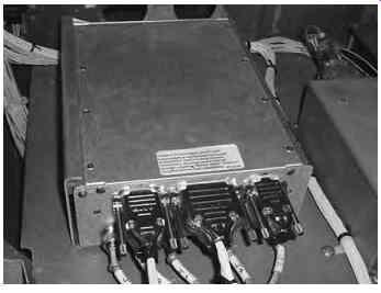
FIG. 7 General aviation connectors (D-shaped)
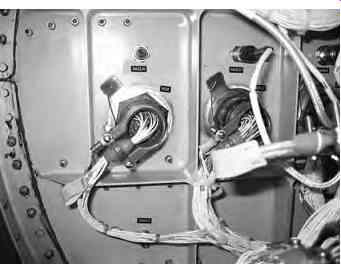
FIG. 8 Circular quick-release connectors
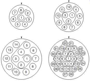
FIG. 9 Pin/socket identification
1.3 Connectors
Wires and cables also have to be routed through bulk heads or production breaks; this is normally achieved by using quick-release connectors. General aviation connectors (D-shaped) are the same type as used on personal computers, see FIG. 7.
Larger aircraft use circular quick-release connectors as shown in FIG. 8. Pins and sockets are crimped onto their respective ends of stripped wires; the connector is assembled usually with a supporting bracket.
Connectors are released by screws or by twisting the quick-release mechanism. Pins and sockets are removed and inserted using special tools; they are crimped onto the wires in a similar way to crimping of tags and splices.
Key maintenance point
If the connector is to be left undone for a period of time, always protect the pins/sockets with a cap or plastic bag.
The bodies and shells of quick-release connectors are made from light alloy, stainless steel or cadmium plated alloys. Keyways ensure the correct alignment and prevent any twisting movement. The pins slide into the respective socket; the pins are gripped by springs inside the socket to provide the electrical con tact surface. A number identifies each pin/socket; see FIG. 9 for examples.
Key maintenance point
Pin/socket numbers of a connector are referenced to a physical point, or marking on the connector.
Key maintenance point
Connector socket spring-grips wear over time and can cause loss of continuity. Inserting anything but the correct pin can cause permanent damage.
Key maintenance point
When re-making connectors, always check the alignment of keyways of mating connectors before making the connection.
1.4 Aluminum wires or cables
Some applications use aluminum wires or cables to save weight. It is essential that the correct procedures, tools and materials are used when working with aluminum wires or cables. Aluminum oxidizes immediately when exposed to air, leading to high-resistance joints; compounds must be used to prevent this.
Petrolatum (semi-solid mixture of hydrocarbons) and granular zinc compounds can either be applied during the crimping process, or be pre-filled within the crimp.
When the crimp joint is made, the compound penetrates around each of the strands; the abrasive action of the compound scours the surfaces and removes the oxidation. When the crimping process is completed, the compound remains in the crimp to form a sealed termination. Aluminum wiring crimps joined into the main aircraft distribution system, it will be joined with relatively hard materials, e.g. copper or steel. Fixing hardware, e.g. nuts, bolts and washers must be made of materials such as cadmium-plated aluminum that will not cause electrolytic corrosion. It is essential that washers are used to protect the softer aluminum material. The surfaces must first be cleaned and treated with compound; the terminations are secured with nuts that must be torque-loaded.
Key maintenance point
Flexing of aluminum wires during installation together with aircraft vibration causes work-hardening leading to brittle joints.
2. Bonding
It is a mandatory requirement that aircraft structure and equipment are electrically bonded. Specific bonding and grounding connections are made in an aircraft to accomplish the following:
-- dissipate energy from a high intensity radiated fields (HIRF) and lightning strikes
-- dissipate static electricity
-- limit the potential difference between equipment
-- provide a low resistance path for earth return systems.
Bonding connections are made between components and structure using purpose-made straps, see FIG. 10 (further examples are given in Section 19). Bonding is categorized as either primary or secondary; this is determined by the magnitude of current being con ducted. Primary bonding is designed for carrying lightning discharges and to provide electrical return paths. Secondary bonding is used to dissipate static electricity and keep all structure at the same potential. Bonding straps (or leads) are pre-fabricated from braided copper or aluminum terminated with crimps.
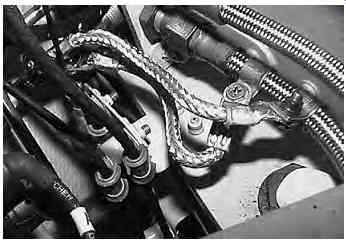
FIG. 10 Bonding
=====
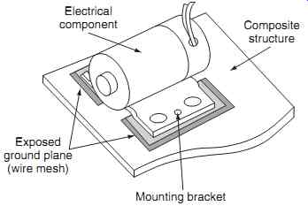
FIG. 11 Direct bonding on composite structure: Exposed ground plane (wire mesh)
====
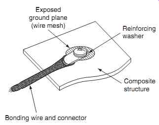
FIG. 12 Indirect bonding on composite structure
==========
2.1 Composite materials
There is an increasing use of composite materials being used in the construction of aircraft because of their good strength-to-weight ratio (compared with aluminum). Composite material has a high electrical resistance and is intrinsically unsuitable for bonding, earth returns and lightning strike dissipation. A ground plane has to be integrated into the airframe; this is normally achieved by bonding an aluminum wire mesh into the composite structure during manufacture. This mesh is accessed at Key points around the aircraft to gain access to the ground plane.
Direct bonding ( FIG. 11) is achieved by exposing the mesh (ground plane) and mounting the equipment directly onto the conductive path. Indirect bonding ( FIG. 12) is achieved by exposing the mesh and installing a bonding wire and connector. The mesh must always be coated after making a connection since the aluminum will oxidize when exposed to air, leading to high resistance and unreliable joints.
Lightning protection in composite aircraft is achieved via aluminum wire integrated into the outer layers of the composite construction. The lightning strike will enter and leave the aircraft at its extremities; the integrated wires are installed in anticipation of this and the energy dissipated through the aircraft along pre-determined routes to the exit point(s).
2.2 Maintenance requirements
Maintenance requirements for bonding include inspection of the two crimped tags to ensure that they are secure and not corroded. The braided conductor should be inspected for any visual signs of mechanical dam age; it must not interfere with any moving items e.g. flying controls or actuators. The bonding lead must have sufficient slack to allow for aircraft flexing. All contacting surfaces must be bare metal; the crimp tags are then treated and sealed in accordance with the maintenance manual. Electrolytic corrosion can occur at the bonding lead connection; it is essential that the correct bonding lead materials and treatments are used.
Key maintenance point
If a bonding lead has to be changed, refer to the aircraft documentation to obtain the correct type and part number.
3. Static charges
Static charges build up on the airframe during flight and these must be discharged into the atmosphere to avoid interference with avionic equipment. Electric charge is dissipated from the surface of an aircraft during flight by an effect called corona discharge. Coronas can generate both audible and radio frequency (RF) noise, thereby disrupting the avionic systems. (Power lines produce an audible sound because they are producing a corona discharge that is interacting with the surrounding air.) Static electricity is discharged from the aircraft to atmosphere through static wicks (FIG. 13), sometimes called static dischargers. These ensure that the discharge of static electricity is from pre-determined points.
Static dischargers are fabricated with a wick of conductive element that provides a continuous low resistance discharge path between the aircraft and atmosphere. The corona discharge can cause a faint glow adjacent to the prominent sections of the air craft, e.g. wing tips; this results from ionization of oxygen and the formation of ozone in the surrounding air. The electric field created by the flow of electrons into the conductive section of the wick contains enough energy to ionize the oxygen and nitrogen in the air. This can produce low-energy plasma, the corona discharge. Plasma is a fourth state of matter along with solids, liquids, and gases. It is similar in appearance to a gas or liquid, but the molecules are separated into atoms from which the electrons in the outer shell are released into the plasma.
Key maintenance point
Helicopters (or rotorcraft) build up additional static charges through their rotor blades.
============
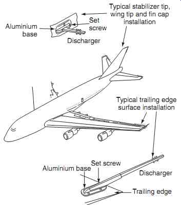
FIG. 13 Static discharger locations
Set screw; Aluminum base; Discharger; Discharger; Trailing edge; Set screw; Aluminum base; Typical stabilizer tip, wing tip and fin cap installation Typical trailing edge surface installation
=======
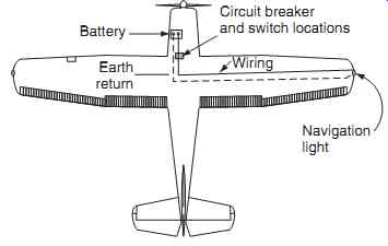
FIG. 14 Airframe ' earth return ' circuit
Circuit breaker and switch locations; Wiring; Navigation light; Earth return
Battery
============
Despite the precautions taken to dissipate static charge during flight, it is highly likely that some charge will remain in the aircraft after landing. This presents a personal shock hazard for crew, passengers and ground staff. Static electricity is dissipated through tyres when the aircraft lands; the tyres are impregnated with a conductive compound. The retained static electricity also presents a major hazard during refueling since the air craft and fuel bowser will almost certainly be at different potentials, thereby causing a spark to jump across the fuel connections. The aircraft and fuel bowser are therefore connected by a length of cable onto specified points before refueling starts.
Key maintenance point
A loose bonding connection causes more problems than having no bonding at all.