AMAZON multi-meters discounts AMAZON oscilloscope discounts
(cont. from part 1)
4. Earth returns
Aircraft with metallic structure use the airframe as the means of completing the electrical circuit, thereby reducing the cost, weight and installation time of installing a return wire, see FIG. 14. In this example, the positive side of the battery power supply is connected to the navigation light via the circuit protection and control switch.
The earth (or ground) return is connected to the negative side of the power supply via the aircraft structure. In some installations, grounding of the load, e.g. the navigation light is via the body of the component's housing. In other installations, all the negative connections are collected at earth stations. (Wires terminating at an earth station are usually identified with a suffix letter N.)
The location of the earth stations depends on a number of factors including the:
-- mechanical strength of the structure
-- current through the connections
-- corrosive effects (dissimilar materials)
-- ease of accessing/making the connections.
It is essential that the ground (or earth points) are not mixed between different types of circuit e.g. AC and digital signals. Using a common return path can lead to corrupted signals as illustrated in FIG. 15(a). Separate return paths ( FIG. 15(b)) should be considered on all new system designs; this separation must be maintained whenever specified in the aircraft manuals.
Taking these factors into account, installations will vary considerably; see FIG. 16 for some examples.
In order to make good electrical contact, there must be minimal resistance between the conductor and structure. Earth stations incorporate an anti-corrosion tag or plate to prevent electrolytic reaction between the base of the assembly and aircraft structure. The stations are usually identified on the adjacent structure by numerals preceded by an asterisk.
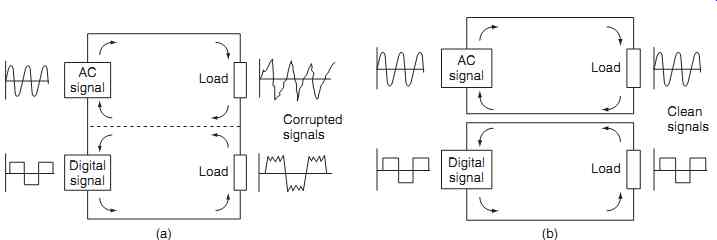
FIG. 15 Earth/ground loops: (a) common return paths, (b) separate return
paths
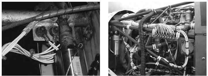
FIG. 16 Earth station installations
Certain circuits must be isolated from each other, e.g. AC neutral and DC earth-returns must not be on the same termination; this could lead to current flow from the AC neutral through the DC system. Relay and lamp returns should not be on the same termination; if the relay earth connection has high resistance, currents could find a path through the low resistance of the filament lamp when cold.
For aircraft that have non-metallic composite structure, an alternative means of providing the return path must be made. This can be in the form of cop per strips running the length of the fuselage or a wire mesh formed into the composite material. The principles of earth return remains the same as with bonding; the method of achieving it will vary.
5. Aircraft manuals
There is a wide range of technical manuals required by certifying staff, including, but not limited to:
-- maintenance manuals
-- illustrated parts catalogues
-- wiring diagram manuals
-- schematic diagrams.
These documents contain information required to explain how equipment operates, how it is maintained, and the correct part numbers that can be used when replacing components. For electrical and electronic systems, additional information is required to show how the systems are supplied with power, interconnections with other systems etc. For larger aircraft, a standardized manual format was developed by the Airline Transport Association (ATA) of America called ATA Spec. 100. This specification contains format and content guidelines for technical manuals written by aircraft manufacturers and suppliers. The format has widespread international acceptance by aircraft manufactures, airlines and equipment suppliers for the maintenance of their respective products. The specification is organized into ATA sections that are specific to an aircraft system, e.g.
ATA Section 24 contains all subjects within the electrical power systems, Section 33 contains details of the aircraft lights. (A complete list of ATA sections is given.) The ATA Spec. 100 is not widely adopted by the general aviation (GA) industry; the information required by certifying staff on GA aircraft is presented in a number of formats. In 2000, ATA Spec 100 (documentation) and ATA Spec 2100 (for inventory management) were incorporated into ATA iSpec 2200.
5.1 Maintenance manual
This is the primary source of information and data for certifying staff. When based on ATA Spec. 100, the maintenance manual (MM) is organized into specific sections for complete systems and/or individual components:
-- detailed description
-- component locations
-- maintenance practices
-- servicing
--removal and installation
-- adjustment /test
-- inspection/checking
Not all of these sections apply to every system and/or individual component.
5.2 Wiring diagram manual
Aside from the aircraft maintenance manual, the primary manuals used by avionic engineers are the wiring diagram manuals (WDMs), schematic diagrams and/or circuit diagrams. Wires and cables should be identified to facilitate installation, trouble-shooting and potential modifications. There are various specifications that provide details of how wiring identification is implemented, including those adopted by the aircraft manufacturers. The simplest form of identifying cables is to mark the ends of the wires with the source and destination of the individual wire or cable.
The wire/cable insulation is marked with indelible ink or laser printing. Wires are sometimes identified by the system type, wire number and gauge. Some manufacturers mark the cables at intervals along the cable.
On more complex installations, where cables are bundled into looms, the entire loom may be given an identification code; this would be marked on a sleeve or band.
When created under ATA Spec. 100, the WDM pro vides details of equipment locations, wiring between equipment and connectors (including wire and cable identification). Schematic diagrams provide an over view of the system interconnections and equipment locations; individual wire numbers and connections are omitted for clarity. In some GA applications, basic electrical and electronic system information is contained within the maintenance manual.
In smaller GA aircraft, much of the avionic equipment is installed as a customer option; in this case, the equipment installer provides the necessary details as supplements. This also applies in the case where new equipment is installed as part of an equipment upgrade. For the majority of cases, symbols used in wiring diagrams and schematics are standardized; however, some variations do exist among manufacturers. Symbols used for electrical and electronic equipment are provided in Appendix 9.
6. Circuit testing
The typical sequence in which electrical and electronic systems are checked and tested is as follows:
-- visual inspection ; this enables obvious faults to be identified and the appropriate action(s) taken
-- bonding test ; this checks the continuity of the earth return path back to the power supply(s)
-- continuity test ; this checks the interconnections between all circuits
-- insulation resistance (IR) test ; this checks for adequate insulation resistance between conductors and between conductors and the airframe (earth)
-- functional test ; there will be varying levels of test depending on complexity of circuit
These range from simple ' self tests ' through to deeper tests that can only be carried out in the workshop.
Key maintenance point
For personal safety and to reduce the risk of dam age to wiring and/or components, isolate power supplies when changing equipment or inspecting interconnecting wiring.
There are a number of techniques used to identify and locate faults in aircraft wiring and equipment, e.g. continuity and resistance measurements. There is a variety of equipment available to the avionics engineer to check and test aircraft electrical and electronic systems, including multimeters and oscilloscopes.
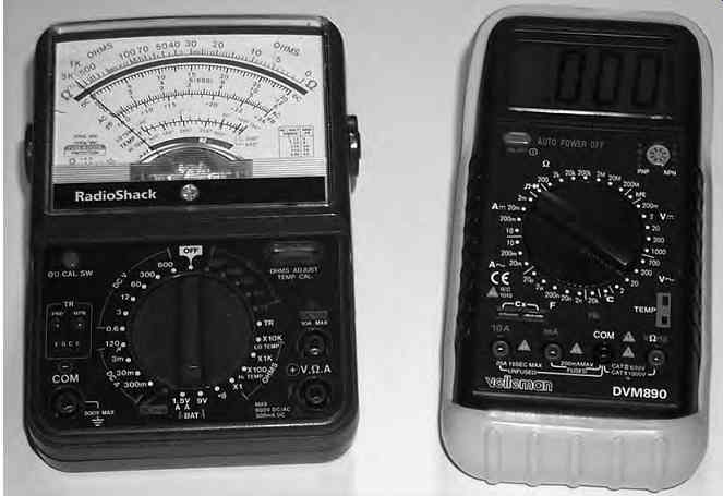
FIG. 17 Multimeter; analogue or digital
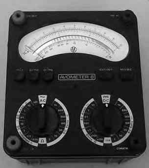
FIG. 18 Avometer (registered trade mark of Megger Group Limited)
6.1 Multimeters
The most popular item of test equipment used for simple troubleshooting is the multimeter; these can be either analogue or digital instruments, see FIG. 17. Multimeters combine several functions into a single item of test equipment; the basic functions on simple multimeter include the measurement of current, volt age and resistance.
6.1.1 Analog instruments
A popular analog instrument used in the aircraft industry is the Avometer (registered trademark of Megger Group Limited). This instrument is often referred to simply as an AVO, deriving its name from the words amperes, volts, ohms. It has been in widespread use in the UK from the 1930s and can still be found in many hangars, workshops and repair stations. Referring to Fig. 18, features include the measurement of:
-- alternating currents up to 10 A
-- voltages up to 1000 V
--resistance from 0.1 Ohm up to 200 k Ohm.
The instrument is very accurate, typically _ 1% of full-scale deflection (FSD) on DC ranges and _ 2% on AC ranges. Maximum current consumption for voltage measurement is 50 µA (corresponding to a sensitivity of 20,000 Ohm per volt); thereby minimizing voltage measurement error. Two rotary switches are used to select the function and range to be measured; if the wrong combination of function or range is selected, an overload cut-out switch (similar to a circuit breaker) disconnects the test circuit. Some multimeters can measure the voltage drop across semiconductor junctions and measure additional circuit/component quantities such as:
-- capacitance
-- frequency
-- temperature
-- conductance
-- inductance.
6.1.2 Digital multimeters
Digital multimeters are generally smaller than the analog type of multimeter making them a useful hand held device for basic fault finding on the aircraft. Higher specification devices can measure to a very high degree of accuracy and will commonly be found in repair shops and calibration laboratories. Digital multimeters offer more features than basic analogue instruments; commonly available measurement features include:
-- autoranging
-- sample and hold
-- graphical representation
-- data acquisition
-- personal computer interface.
Autoranging selects the appropriate range for the quantity under test so that meaningful digits are shown. For example, if a battery cell terminal voltage of 1.954 VDC was being measured, autoranging by a four-digit multimeter would automatically display this voltage instead of 0.019 (range set too high), or 0.999 (range set too low) via manual range selection.
Sample and hold retains the most recent display for evaluation after the instrument is disconnected from the circuit being tested. Graphical representation of the quantity under test can be displayed in a number of ways, e.g. as a bar graph. This facilities observations of trends. Simple data acquisition features are used in some multimeters to record maximum and minimum readings over a given period of time, or to take a number of sample measurements at fixed time intervals. Higher-specification multimeters feature a personal computer interface, typically achieved by infrared (IR) links, or datalink connections, e.g. RS-232 or universal serial bus (USB). This interface allows the multimeter to upload measured data into the computer for storage and/or analysis.
6.2 Bonding meters
Aircraft bonding is tested with a bonding meter; the maintenance manual will define specific points on the airframe where measurements are made. The maximum resistance between specific points will be defined in the maintenance manual. The bonding meter consists of a low reading ohmmeter and two leads. One lead is 60 feet long with a single prodded end-piece; the other lead is 6 feet long with a double prodded end-piece. (Note that these leads must never be shortened.) The bond meter is first checked by:
-- shorting all three prods together to check for zero-reading
-- momentarily short the two prods of the 6 feet lead to check for full-scale deflection.
The maximum resistance for between extremities of fixed portions of a metallic aircraft and between bonded components/earth stations will be stated in the maintenance manual; the typical maximum value is 0.05 ohms for an aircraft with metal structure. The maximum value for composite aircraft will vary from type to type, but it will by necessity be very low.
6.3 Oscilloscopes
The oscilloscope (often referred to as a 'scope' ) is an item of electronic test equipment used to measure and view signal voltages as a two-dimensional graph (usu ally signal voltage on the vertical axis versus time on the horizontal axis). The oscilloscope will be found in most workshops, repair stations and calibration laboratories, see FIG. 19.
Original equipment was based on the cathode ray tube (CRT) display, making them heavy and bulky.
Use of liquid crystal display (LCD) technology makes the oscilloscope useful as a portable device.
(More information is provided on CRTs and LCDs in a related title in the series: Aircraft Digital and Electronic Computer Systems.) The portable oscilloscope has many uses during troubleshooting, e.g. checking for electrical noise and measurement of dig ital signals. PC-based oscilloscopes can be configured in an existing laptop via a specialized signal acquisition board and suitable hardware interfaces; the PC based oscilloscope has a number of features:
-- lower cost compared to a stand-alone oscilloscope
-- efficient exporting of data into standard PC software, e.g. spreadsheets
-- control of the instrument via custom programs on the PC
-- utilization of the PC's networking and disc storage functions
-- larger-/higher-resolution color displays
-- colors can differentiate between waveforms
-- portability
7. Automatic test equipment
Automatic test equipment (ATE) is dedicated ground test equipment that provides a variety of different functional checks on line-replaceable units (LRUs) or printed circuit boards (PCBs). The equipment being tested is connected to a variety of external circuits that represent the aircraft interfaces; addition connections are often made for diagnostic purposes. ATE is able to gather and analyze a large amount of data very quickly, thus avoiding the need to make a very large number of manual measurements in order to assess the functional status of an item of equipment.
ATE usually incorporates computerized control with displays and printouts that indicate what further action (repair or adjustment) is necessary in order maintain the equipment. Equipment may then require further detailed tests and measurements following initial diagnosis. ATE tends to be dedicated to a particular type of avionic system; it is therefore expensive to develop, manufacture and maintain. Because of this, ATE tends to be only used by original equipment manufacturers (OEMs) and licensed repairers.
8. On-board diagnostic equipment
Systems have been developed to match the complexity of electrical and electronic systems to assist the avionics engineer in fault finding on aircraft systems.
On-board diagnostics use a range of techniques that are built into and integrated with the aircraft systems.
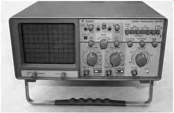
FIG. 19 Oscilloscope
8.1 Built in test equipment
As the name implies, built-in test equipment (BITE) is primarily a self-test feature built into aircraft electrical and electronic equipment as a means of:
-- detecting and indicating specific equipment faults
-- monitoring equipment performance
-- detecting problems
-- storing fault data
-- isolate faulty sensors/components
The origins of BITE started with simple on/off displays on the front of line replaceable units (LRU) to assist the avionics engineer with troubleshooting; this display (typically a light-emitting diode, LED) would indicate the go/no-go status for a particular unit, either as a result of system test or in-flight fault. If the LED indicates an LRU fault, the engineer either changes the LRU or check the interfaces with the unit. This simple technique is applied to individual LRUs, and will only indicate real-time faults. BITE techniques were developed alongside the increasing complexity of electrical and electronic equipment.
Features such as fault storage provide an indication of faults over many flights; this information is often provided in coded form and needs to be interpreted by the engineer.
BITE is usually designed as a signal flow type test. If the signal flow is interrupted or deviates out side accepted levels, warning alerts indicate a fault has occurred. The functions or capabilities of BITE include the following:
--real-time monitoring of systems
-- continuous display presentation
-- sampled recorder readouts
-- module and/or subassembly failure isolation
-- verification of systems status
-- go/no-go indications
-- quantitative displays
-- degraded operation status
-- percentage of functional deterioration
8.2 Centralized maintenance systems (CMS)
BITE technology has now been developed into centralized maintenance systems on modern aircraft.
The electronic centralized aircraft monitoring sys tem (ECAM) developed for Airbus aircraft oversees a variety of aircraft systems and also collects data on a continuous basis. While ECAM automatically warns of malfunctions, the flight crew can also manually select and monitor individual systems. Failure messages recorded by the flight crew can be followed up by maintenance personnel by using the system test facilities on the maintenance panel in the flight compartment. Printouts can be produced as permanent records for further analysis, see FIG. 20.
Dedicated CMS control display units (CDU) are installed on the center pedestal. The CDU allows systems to be investigated via a menu selection; this provides a description of the flight deck effect (FDE) and likely reasons for the fault. Typical centralized maintenance systems have a dedicated centralized maintenance computer (CMC) to collect, analyze and store fault information. The CMC has up to 50 data bus inputs, 10 data bus outputs and can store up to 500 fault messages into non-volatile memory (NVM).
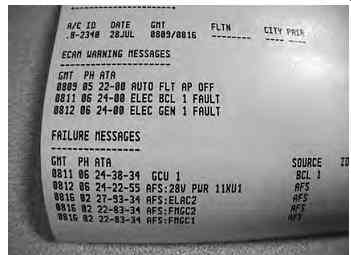
FIG. 20 ECAM printout
8.3 Aircraft communication addressing and reporting system
Some aircraft are installed with a system called ACARS (aircraft communication addressing and reporting sys tem). This is a digital data link system transmitted in the VHF range (118 MHz to 136 MHz). ACARS pro vides a means by which aircraft operators can exchange maintenance and operational data directly without human intervention. This makes it possible for airline staff to communicate directly with the aircraft in their fleet in much the same way as it is possible to exchange data using a land-based digital network. ACARS uses an aircraft's unique identifier and the system has some features that are similar to those currently used for electronic mail. Typical ACARS messages are used to convey routine information such as:
-- fuel data
-- engine performance data
-- aircraft fault data
-- passenger loads
-- departure reports
-- arrival reports
This information can be requested by the company and retrieved from the aircraft at periodic intervals or on demand. Prior to ACARS this type of information would have been transferred via VHF voice communications. (Additional information on ACARS is provided a related guide in the series: Aircraft Communications and Navigation Systems. )
9. QUIZ-- Multiple choice questions
1. ACARS is a digital data link system transmitted in the:
(a) VHF range
(b) LF range
(c) UHF range.
2. Secondary bonding is designed for:
(a) carrying lightning discharges through the aircraft
(b) keeping all the structure at the same potential
(c) discharging static electricity from the aircraft to atmosphere.
3. Some electrical installations use aluminum wires or cables to:
(a) reduce EMI
(b) save cost
(c) save weight.
4. Visual inspection of wiring installations:
(a) enables obvious faults to be identified and the appropriate action(s) taken
(b) checks for adequate insulation resistance between conductors
(c) checks the continuity of the earth return path back to the power supply(s).
5. In terms of bonding, composite material has a:
(a) high resistance and is unsuitable for bonding
(b) low resistance and is unsuitable for bonding
(c) high resistance and is suitable for bonding.
6. For a given wire size, when installed in a loom it will be able to safely conduct:
(a) more current compared to a wire in free circulating air
(b) less current compared to a wire in free circulating air
(c) the same current compared to a wire in free circulating air.
7. Bonding is categorized as primary or secondary determined by the:
(a) use of composite or metal structure
(b) locations of static wicks
(c) magnitude of current being conducted.
8. The use of composite materials for aircraft structures results in:
(a) less natural paths for bonding
(b) more natural paths for bonding
(c) higher probability of a lightning strike.
9. Bonding is made between components and structure using:
(a) coaxial cable
(b) purpose-made straps
(c) general-purpose wiring.
10. Static electricity is discharged from the aircraft to atmosphere through:
(a) composite structure
(b) earth stations
(c) static wicks