AMAZON multi-meters discounts AMAZON oscilloscope discounts
(cont. from part 1)
4. Lightning
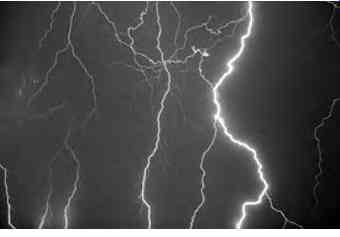
Lightning together with precipitation is associated with electrical activity within cumulonimbus clouds, see FIG. 9. Lightning results from the build up of huge amounts of static charge in the atmosphere.
Precipitation may defined as the result of water vapor condensing in the atmosphere that subsequently falls to the earth's surface.
Electrical activity can originate at the top of thunderclouds or the outside edges of the precipitation area. If an aircraft is subjected to a lightning strike, or discharge, the structure and bonding are designed to dissipate this energy, see FIG. 10.
=========
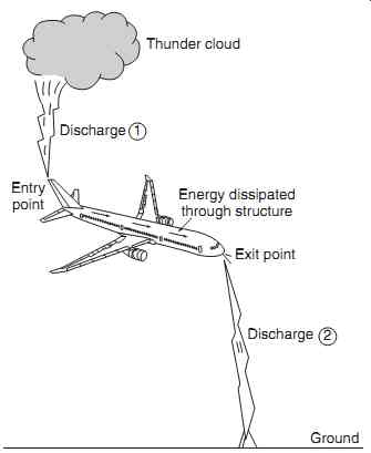
FIG. 10 Lightning strike; dissipation of energy through the aircraft
Energy dissipated through structure Exit point Discharge Ground Entry point Discharge Thunder cloud 2 1
==========
===========
Key maintenance point
The probability of an aircraft experiencing a lightning strike on any given flight is one. High standards of design and maintenance are required to ensure that serious damage from a lightning strike is a rare occurrence.
4.1 Faraday cage
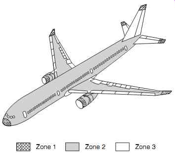
The metallic aircraft structure acts as a Faraday cage (or Faraday shield), named after the British physicist Michael Faraday. This is an enclosure formed by a conducting material that shields the inside of the structure from electromagnetic effects. An external electrical field will cause the electrical charges within the structure to redistribute themselves so as to cancel the field's effects inside the fuselage. This effect is used very effectively in aircraft to protect electronic equipment from lightning strikes and other electrostatic discharges. Lightning normally enters the aircraft at an extremity, e.g. the nose cone or wing tip; currents flow through the conductive structure, and then exits the aircraft at another extremity. This can cause short-term interference with systems, but there should be no permanent damage. Some currents could enter the structure due to the high voltages, the energy will normally be conducted through bonding leads and back into the fuselage skin. The aircraft is categorized into specific areas when planning system and equipment locations, see FIG. 11:
-- zone one is where lightning can be expected to enter and exit the aircraft
-- zones two and three provide the conductive paths through the aircraft.
Key maintenance point
The majority of physical damage on the aircraft occurs at the exit point of the lightning strike.
4.2 Aircraft construction
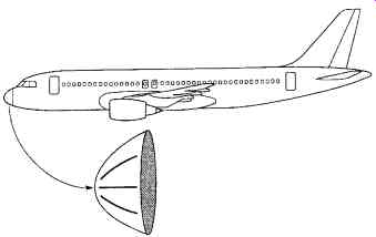
The metal structure dissipates electric currents generated from the external electromagnetic fields, thereby reducing or even eliminating electromagnetic interference. More aircraft are now being built using (non-conducting) composite materials, ranging from individual items of structure through to the complete exterior. In this case, the Faraday cage effect has to be designed into the composite structure as a mesh of conducting material. Additional design effort, testing and on-going maintenance are required as a con sequence. One particular part of the aircraft often affected by lighting is the nose cone; this is made from a composite material and therefore has no inherent conductive paths. Lightning strips can be fitted to protect this area, see FIG. 12
Key maintenance point
The aircraft is designed to provide conductive paths to dissipate the energy from lightning strikes. Over periods of time, certain parts of the aircraft will corrode and be subjected to vibration; it is essential that these conducive paths are maintained, e.g. by inspection of bonding leads.
Even when the lightning discharge is dissipated safely through the aircraft, structural damage can occur at the exit points of the discharge. Furthermore, the high circulating currents can causes EMI as previously discussed. Lightning discharges via the atmosphere from one cloud to another, or directly to the earth's surface. The atmosphere has a very high dielectric breakdown (depending on moisture content), typically three million volts per meter. The voltage generated by lightning depends on the length travelled by the lightning discharge; this will be approximately one gigavolt (10^9 volts) for a 300 m (1000 ft) lightning bolt. With a typical current of 100 kA, this gives rise to a power dissipation of 100 terawatts (100 x 10^12 watts). The high energy radiated by a lightning discharge carries sufficient electromagnetic field strength to couple into the aircraft's wiring. This causes high currents of relatively short duration to be injected into electronic equipment. Adequate protection must be designed into the equipment to prevent disruption of signal processing and/or damage to components.
===========
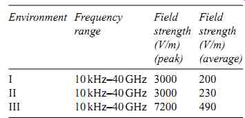
Table 1 External HIRF environments
Environment Frequency range
Field strength (V/m) (peak)
Field strength (V/m) (average)
I 10 kHz-40 GHz 3000 200
II 10 kHz-40 GHz 3000 230
III 10 kHz-40 GHz 7200 490
============
4.3 Certification of aircraft for HIRF and lightning protection
Although the sources of HIRF and lightning (HIRF/L) threats are very different, the strategies used in design, certification and maintenance are very similar, if not the same. The external HIRF and lightning (HIRF/L) environment has evolved over time and varies between aircraft types. Various specifications defining HIRF/L threat levels have emerged in response to the increasing understanding of the problem. In Europe, aircraft have been required to comply with HIRF requirements since early 1992. In-service aircraft are therefore specified with varying HIRF standards ranging from no requirement through to the current standards. HIRF threat levels can be broadly thought of in terms of field strength and frequency of the RF signal. Compliance with HIRF requirements typically involves a range of factors including:
-- testing the entire aircraft
-- equipment tests
-- analogy/similarity with other installations
Equipment and systems being certified for HIRF/L immunity and susceptibility are in fact achieved by any combination of the above. Comprehensive test programs are required on new aircraft types; this is carried out on entire aircraft, with engines and systems operating. Various techniques are used for HIRF/L testing:
-- bulk current injection (BCI) via a probe that injects RF signals directly into wire bundles when clamped around them.
-- direct drive testing (DDT) involves connecting an RF signal source directly to the unit being tested.
Testing is an expensive and time-consuming activity, one that has to be planned and agreed with the certifying authorities well in advance of the aircraft going into service. An alternative strategy is to use existing HIRF compliance documentation and data from a similar system (or aircraft) to demonstrate HIRF compliance. Failure conditions resulting from HIRF/L are assessed against certification requirements and are given classifications, i.e. catastrophic, hazardous or major. The classifications for HIRF/L related system failures are assigned certification levels of:
A. Catastrophic: where system failure(s) would prevent the continued safe flight and landing of the aircraft;
B. Hazardous: where system failure would significantly reduce the capability of the aircraft and/or the ability of the flight crew to respond to the failure(s);
C. Major: where system failure reduces the capability of the aircraft or the ability of the flight crew to respond to an adverse operating condition(s).
A safety assessment is prepared to address all potential adverse effects. The safety assessment could establish that some systems have different failure conditions in different phases of flight, e.g. a navigation system may have a catastrophic failure condition during the landing phase, but in cruise the classification could be reduced to a major failure condition.
To cater for these different classifications on the same system, varying HIRF environments would be applied, see Table 1.
The field strength values shown in Table 1 are the maximum for any given frequency within the range. Field strength values are expressed in root mean-square (RMS) units, measured during the peak of the modulation cycle.
4.4 Maintenance for HIRF/L protection
The maintenance engineer has a number of essential tasks to ensure that HIRF/L protection features and devices are serviceable for continued airworthiness of the aircraft. These tasks include, but are not limited to:
-- bonding resistance measurements
-- wire/cable resistance or impedance measurements
-- inspection and disassembly of connectors to detect corrosion or termination failure.
4.5 Aircraft wiring and cabling
When many potential sources of EMI are present in a confined space, aircraft wiring and cabling has a crucial role to play in maintaining electromagnetic compatibility. Adequate wire separation should be maintained between noise source wiring and susceptible equipment. For example, radio-frequency (RF) navigation systems' wiring should be strategically routed in the aircraft to ensure a high level of EMC. Any changes to the routing of RF systems ' wiring could have an adverse affect on EMC. Separation requirements for all wire categories must be maintained; wire lengths should be kept as short as possible to maintain coupling at a minimum. Where wire shielding is incorporated to protect against EMI caused by lightning, it is important that the shield grounds (pigtails) be kept to their designed length. An inch or two added to the length will result in degraded lightning protection.
Equipment grounds must not be lengthened beyond design specification. A circuit ground with too much impedance may no longer be a true ground.
Key maintenance point
With the aid of the aircraft technical manuals, grounding and bonding integrity must be maintained. This includes proper preparation of the surfaces where electrical bonding is made.
5. Grounding and bonding
The aircraft structure provides an extremely important means of reducing EMI and also protecting the aircraft, its passengers, crew and systems, from the effects of lightning strikes and static discharge.
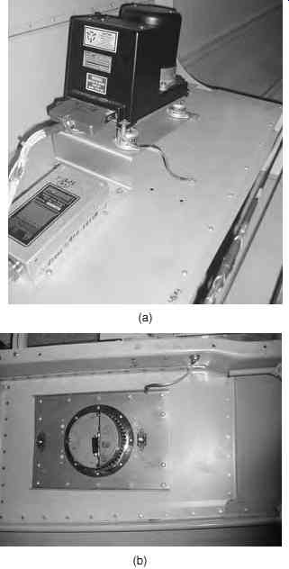
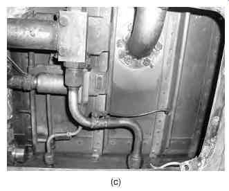
Grounding and bonding are specific techniques that are used to achieve electrical integrity, see FIG. 13.
Grounding and bonding can also be instrumental in minimizing the effects of high-intensity radiated
fields (HIRF) emanating from high-power radio transmitters and radar equipment. Grounding and bonding resistances of less than 0.001 ohms to 0.003 ohms are usually required.
Grounding can be defined as the technique of electrically connecting components to either a conductive structure or another return path for the purpose of completing a circuit. Bonding refers to the electrical connecting of two or more conducting objects that are not otherwise adequately connected. Bonding and grounding connections are made in an aircraft in order to accomplish the following:
-- dissipate energy from a high-intensity radiated fields (HIRF) and lightning strikes
-- dissipate static electricity
-- limit the potential difference between equipment
-- provide a low resistance path for earth return systems.
The following general procedures and precautions apply when making bonding or grounding connections:
-- bond or ground parts to the primary aircraft structure where possible
-- make bonding or grounding connections so that no part of the aircraft structure is weakened
-- bond parts individually if feasible
-- install bonding or grounding connections against smooth, clean surfaces
-- install bonding or grounding connections so that vibration, expansion or contraction, or relative movement in normal service, will not break or loosen the connection
-- check the integrity and effectiveness of a bonded or grounded connection using an approved bonding tester.
The main types of bonding are: Equipment bonding. Low impedance paths to the aircraft structure are generally required for electronic equipment to provide radio-frequency return circuits and to facilitate reduction in EMI. Metallic surface bonding. All conducting objects located on the exterior of the airframe should be electrically connected to the airframe through mechanical joints, conductive hinges, or bond straps, which are capable of conducting static charges and currents induced by lightning strikes.
Static bonds. All isolated conducting paths inside and outside the aircraft with an area greater than 3 in.² and a linear dimension over 3 inches that are subjected to electrostatic charging should have a mechanically secure electrical connection to the aircraft structure of adequate conductivity to dissipate possible static charges.
6. Electrostatic sensitive devices (ESSD)
Advances in electronic technology bring many new features and benefits, e.g. faster processors, higher density memory and highly efficient displays. These advances are primarily due to the reduction in the physical size of semiconductor junctions; this leads to higher-density components in given size of integrated circuit. One significant problem associated with the handling of semiconductor devices is that the smaller junctions are susceptible to damage from electrostatic voltages. An example of static electricity that the reader might have encountered is the electric shock received when stepping out of a car.
The synthetic materials used for clothing as well as the vehicle's interior are capable of producing large amounts of static charge which is only released when the driver or passenger sets foot on the ground!
6.1 Triboelectric effect
When two dissimilar non-conducting materials are rubbed together, the friction transfers electrical charge from one material to the other. This raises the electrical potential between the materials, and is known as the triboelectric effect. The build-up of charge, and subsequent attraction of materials, can be observed when cling film is separated from its roll. The polarity and strength of the electrical charges depend primarily on the materials, surface finish, ambient tempera ture and humidity. The triboelectric series classifies different materials according to how readily they create static electricity when rubbed with another material. The series is arranged on a triboelectric scale of increasingly positive and increasingly negative materials.
============
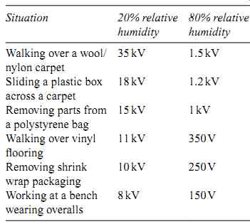
Table 2 Representative values of electro static voltages generated in typical
work situations
Situation 20% relative humidity
80% relative humidity
Walking over a wool/ nylon carpet
35 kV 1.5 kV
Sliding a plastic box across a carpet
18 kV 1.2 kV
Removing parts from a polystyrene bag
1 5 k V 1 k V
Walking over vinyl flooring
11 kV 350 V
Removing shrink wrap packaging
10 kV 250 V
Working at a bench wearing overalls
8 kV 150 V
=============
Materials that give up electrons and become positive when charged (thereby appearing as positive on the triboelectric scale) include glass, air and dry human skin. Materials that attract electrons become negatively charged (appearing as negative on the triboelectric scale) include:
-- polyester
-- polystyrene
-- polyethylene
-- poly(vinyl chloride) (PVC)
Certain materials do not readily attract or give up electrons when brought in contact or rubbed with other materials are neutral on the triboelectric scale; examples include cardboard, cotton and steel.
The largest amounts of static charge resulting from materials being rubbed together (or separated from each other in the case of cling film) are at the extreme ends of the triboelectric scale. For example, PVC rubbed against glass or polyester rubbed against dry human skin both produce an accumulation of charge. A common occurrence when working in a dry atmosphere is that people rapidly discharge current (sometimes producing a spark) when touching metal objects. This is because they have relatively dry skin (which can become highly positive in charge), and is accentuated when the clothes they wear are made of man-made material (such as polyester), which will acquire a negative charge. The effect is much less pronounced in a humid atmosphere where the stray charge can 'leak away ' harmlessly into the atmosphere. (Note that moist skin tends to dissipate charge more readily.) People that build up static charges due to dry skin are advised to wear all-cotton clothes since cotton is neutral on the triboelectric scale.
6.2 Working environment
The problem for the electronics industry is that high voltages can be accumulated in people and materials and then discharged into equipment. This discharge can weaken and/or damage electronic components.
Representative values of electrostatic voltages generated in some typical working situations are shown in Table 2. (Note the significant difference in voltage generated at different values of relative humidity.)
Static voltage susceptibility varies for different types of semiconductor device or components, for example static discharge voltages as low as 20 V t o 100 V can affect complex devices such as microprocessors. Single components such as silicon-controlled rectifiers are not affected until levels of between 4 kV to 15 kV are reached.
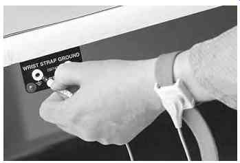
FIG. 15 ESD Typical wrist strap grounding point
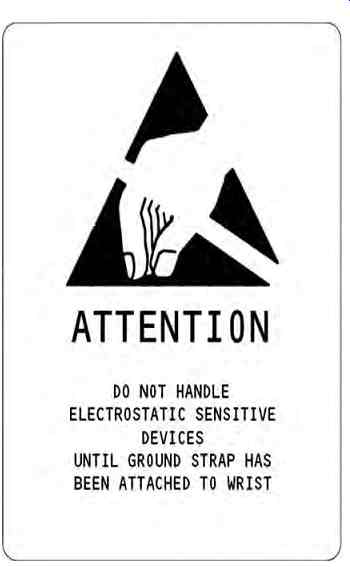
Electrostatic sensitive devices (including printed circuit boards, circuit modules, and plug-in devices) are invariably marked with warning notices. These are usually printed with black text on yellow back grounds, as shown in FIG. 14.
Special precautions must be taken when handling removing ESSD. These precautions include use of the following:
-- wrist/heel straps
-- static dissipative floor and bench mats
-- ground jacks
-- grounded test equipment
-- low-voltage soldering equipment and anti-static soldering stations (low-voltage soldering irons with grounded bits)
-- anti-static insertion and removal for integrated circuits
-- avoidance of nearby high-voltage sources (e.g. fluorescent light units)
-- anti-static packaging (static-sensitive devices and printed circuit boards should be stored in their anti-static packaging until such time as they are required for use)
-- Protective materials
Wrist straps (and also heel straps) are conductive bands that are connected to an effective ground point by means of a short wire lead. The lead is usually fitted with an integral 1 M-Ohm resistor which minimizes currents arising between the person wearing the strap and the equipment being worked on. Wrist straps are usually stored at strategic points on the aircraft, or they may be carried by maintenance technicians.
FIG. 15 shows a typical wrist strap being used for a bench operation. The bench itself must be grounded; this is achieved by connecting the conductive mat to an external earthing point outside of the building (FIG. 16).
There are three main classes of materials used for protecting static sensitive devices. These are:
-- conductive materials, e.g. metal foils
-- static dissipative materials (a cheaper form of conductive material)
-- anti-static materials, e.g. cardboard and cotton
Of these, conductive materials offer the greatest protection whilst anti-static materials offer the least protection. The working environment plays an important part in the safe handling of ESSD; extra vigilance is required when the relative humidity is low, e.g. in air conditioned workshops. (Further reading on the subject of EMI and ESSD can be found in a related guide in the series, Aircraft Digital and Electronic Computer Systems.)
===========
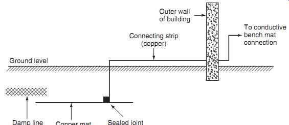
FIG. 16 ESD work area protection
Ground level; Damp line; Copper mat; Sealed joint; Connecting strip (copper); To conductive bench mat connection; Outer wall of building
===========
Key maintenance point
The effect of lower humidity on ESSD components in typical working environments will be to create higher voltages and pose more threat to the components.
7. QUIZ-- Multiple choice questions
1. The ability of an item of equipment to operate alongside other items of equipment without causing EMI is called:
(a) EMC
(b) ESSD
(c) HIRF.
2. Higher-frequency signals can lead to cross-talk between wires as a result of the:
(a) dielectric effect of the wire insulation causing increased capacitance
(b) dielectric effect of the wire insulation causing reduced capacitance
(c) dielectric effect of the wire conductors causing reduced capacitance.
3. Radio and radar transmitters in the external environment are sources of:
(a) EMC
(b) ESSD
(c) HIRF
4. Of the materials used for protecting static sensitive devices:
(a) conductive and anti-static materials offer the least protection
(b) conductive materials offer the least protection whilst anti-static materials offer the most protection
(c) conductive materials offer the greatest protection whilst anti-static materials offer the least protection.
5. Shielding of conductors:
(a) reduces radiation and minimizes susceptibility
(b) increases radiation and minimizes susceptibility
(c) reduces radiation and increases susceptibility.
6. The presence of unwanted voltages or currents in systems is caused by:
(a) EMC
(b) ESSD
(c) EMI.
7. When the lightning discharge is dissipated safely through the aircraft, structural damage is most likely to occur at the:
(a) bonding between structures
(b) exit points of the discharge
(c) entry points of the discharge.
8. In the context of EMI, high-frequency signals should be:
(a) filtered out of a circuit wherever possible
(b) introduced into a circuit wherever possible
(c) used only in unshielded cables.
9. The twisted pair is designed to:
(a) maximize cross - talk between adjacent pairs of wires
(b) protect static sensitive devices
(c) minimize cross - talk between adjacent pairs of wires.
10. The effect of lower humidity on ESSD components in typical working environments will be to:
(a) create lower voltages and pose more threat to the components
(b) create higher voltages and pose more threat to the components
(c) create higher voltages and pose less threat to the components.
