AMAZON multi-meters discounts AMAZON oscilloscope discounts
One of the consequences of operating electrical and electronic equipment is the possibility of disturbing, or interfering with, nearby items of electronic equipment. The term given to this type of disturbance is electromagnetic interference (EMI). Placing a portable radio receiver close to a computer and tuning through the radio's wavebands can illustrate this effect. The computer will radiate electromagnetic energy; this is received by the radio and heard as 'noise'. Radio equipment is designed to receive electromagnetic energy; however, the noise in this simple experiment is unwanted. Electrical or electronic products will both radiate and be susceptible to the effects of EMI. This is a paradox since many principles of electrical engineering are based on electromagnetic waves coupling with conductors to produce electrical energy and vice versa (generators and motors). Furthermore, systems are specifically designed to transmit and receive electromagnetic energy, i.e. radio equipment. The problem facing aircraft electrical and electronic systems is the unwanted noise; in the case of the computer/radio experiment, this unwanted noise is no more than a nuisance. In complex avionic systems, the consequences of EMI can be more serious. The ability of an item of equipment to operate alongside other items of equipment without causing EMI is electromagnetic compatibility (EMC).
Modern digital equipment operates at very high speed and relatively low power levels. In addition to EMI, high-intensity radiated fields (HIRF) are received from the external environment, e.g. from radio and radar transmitters, power lines and lightning. The high energy created by these radiated fields disrupts electronic components and systems in the aircraft. (This effect is also referred to as high-energy radiated fields - HERF.) The electromagnetic energy induces large currents to flow, causing direct damage to electronic components together with the secondary effects of EMI.
Advances in electronic technology bring many new features and benefits, e.g. faster processors, higher density memory and highly efficient displays. These advances are primarily due to the reduction in the physical size of semiconductor junctions; this leads to higher-density components in given size of integrated circuit. One significant problem associated with the handling of semiconductor devices is that the smaller junctions are susceptible to damage from electrostatic voltages. This is a problem that can potentially affect a wide range of electronic equipment fitted in an aircraft. Effects range from weakening of semiconductor junctions through total failure of the equipment; both these effects can occur without any visible signs of damage to the naked eye! Electrostatic sensitive devices (ESSD) are electronic components that are prone to damage from stray electrical charge produced primarily from human operators. This problem is particularly prevalent with high-density memory devices and electronic displays. Weakening and damage to static sensitive devices can result from mishandling and inappropriate methods of storage.
This section looks at some of the practical aircraft maintenance aspects of EMI, EMC and HIRF together with background information and specific guidance on the correct handling and storage of ESSD.
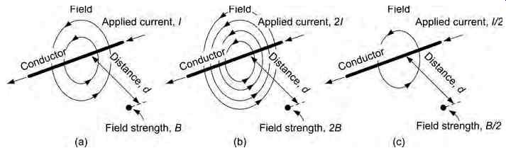
FIG. 1 Current-carrying conductor
==========
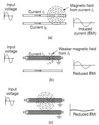
FIG. 2 Shielding principles: (a) conductors unshielded, (b) one conductor
shielded, (c) both conductors shielded
(a) Current I1 Current I2 Input voltage Magnetic field from current I1 Induced current (EMI) (b) Current I1 Input voltage Weaker magnetic field from I1 Reduced EMI (c) Input voltage Reduced EMI
===========
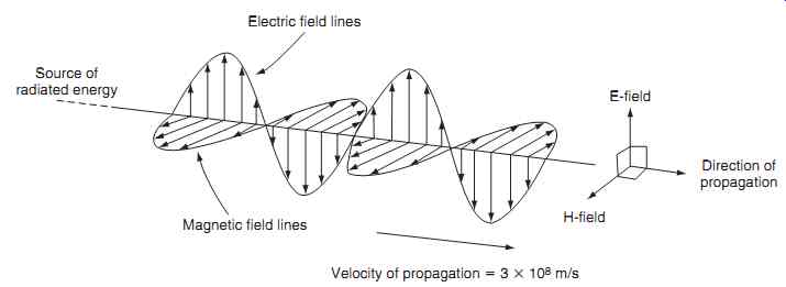
FIG. 3 E and H lines mutually at right angles
Electric field lines; Source of radiated energy; Magnetic field lines; Velocity of propagation = 3 x10⁸ m/s; Direction of propagation; E-field H-field
===========
1. Electromagnetic Interference
Electromagnetic interference (EMI) can be defined as the presence of unwanted voltages or currents that can adversely affect the performance of an electrical/ electronic system. The effects of EMI include:
-- errors in indications
-- unwanted noise on audio signals
-- random patterns on electronic displays
-- repetitive ' buzzing ' on intercom and cabin phone systems
-- desensitizing of radio and radar receivers
-- false indications in radar and navigation equipment
-- nuisance triggering of alarms
Consider the current-carrying conductor illustrated in FIG. 1. It can be seen that the field strength is a measure of flux density at any given point. From first principles, the field strength B is proportional to the applied current and inversely proportional to the distance from the conductor. If an alternating current is applied to the conductor, this field will build up and collapse around the conductor. If a second conductor is now placed alongside the first conductor, the alternating field from the first conductor will induce cur rents in the second conductor. These induced currents will be superimposed onto any current flowing in the second conductor. The first conductor is radiating EMI; the second conductor is susceptible to EMI.
The total EMI effect depends primarily on the amount of current in the first conductor, rate of change of current (i.e. alternating, digital or switched cur rents) and the distance between the two conductors.
Alternating currents, or digital signals being carried by a conductor, will set up alternating magnetic fields thus causing EMI as described. In summary, the amount of electromagnetic field radiated from a conductor depends on amount of current in the conductor and the rate of change of a magnetic field from the conductor.
Key maintenance point
EMI can also be created if a conductor carrying direct current is vibrated close to another conductor. The net result is relative movement of a magnetic field over a conductor with the consequences of induced currents. Wiring looms must be secured to prevent them vibrating excessively.
1.1 Shielding
For a given current, the distance between conductors and the provision of shielding (or screening) are the main considerations when trying to design and install wiring and equipment to minimize EMI. From FIG. 1 we can see that the distance between conductors has a direct effect on the amount of unwanted current induced into the second conductor. The addition of shielding on conductors limits the coupling of electromagnetic fields, see FIG. 2. The electromagnetic field created by current I1 in the first conductor induces a current I2 in the second conductor.
With one conductor shielded, some of the electro magnetic field created by current I1 induces current in the shielding; this current and taken away to a ground connection at one or both ends of the shielding. The shielding effectively absorbs some of the electromagnetic field created by I1; the remaining (weaker) field induces a reduced current I2 in the second conductor.
If both conductors are shielded, most of the weaker field created by I1 is absorbed into the shielding of the second conductor; this further reduces the current I2 in the second conductor.
Shielding can reduce the coupling of electro magnetic fields between conductors. The amount of reduction depends upon the screening material used, its thickness, and the frequency of the applied cur rent. Typical materials used for shielding are metallic mesh, or braiding formed on the outside of the conductor's protective sheath; this ensures that the wire or cable retains some degree of mechanical flexibility.
The shielding impedes the radiation of signals from the first conductor, and also minimizes signals from being induced into the second conductor.
1.2 Electromagnet waves
We have been using the term electromagnet wave to develop the concept of EMI. The electromagnet wave actually comprises two components. As with light, electromagnet waves propagate outwards from a source of energy (transmitter) and comprise electric (E) and magnetic (H) fields at right angles to each other. These two components, the E -field and the H -field, are inseparable. The resulting wave travels away from the source with the E and H lines mutually at right angles to the direction of propagation, as shown in FIG. 3.
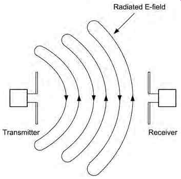
FIG. 4 Radio transmitters and receivers
Electromagnet waves are said to be polarized in the plane of the electric (E) field. Thus, if the E-field is vertical, the signal is said to be vertically polarized whereas, if the E-field is horizontal, the signal is said to be horizontally polarized.
In the case of intentional propagation of electro magnet waves, i.e. radio transmitters and receivers ( FIG. 4), the electric E-field lines are shown in the space between a transmitter and a receiver. The transmitter aerial (or antenna) is supplied with a high frequency alternating current. This gives rise to an alternating electric field between the ends of the aerial/antenna and an alternating magnetic field around (and at right angles to) it. The direction of the E–field lines is reversed on each cycle of the signal as the wavefront moves outwards from the source.
The receiving aerial/antenna intercepts the moving field, and voltage and current is induced as a consequence. These voltages and currents are similar (but of smaller amplitude) to those produced by the transmitter. Note that in FIG. 4 (where the transmitter and receiver are close together) the radiated E-field is shown spreading out in a spherical pattern (this is known more correctly as the near field). The magnetic field (not shown) will be perpendicular to the E-field.
In practice, there will be some considerable distance between the transmitter and the receiver and so the wave that reaches the receiving aerial/antenna will have a plane wavefront. In this far field region, the angular field distribution is essentially independent of the distance from the transmitting antenna.
(Radio wave theory is addressed in more detail in a related book in the series, Aircraft Communications and Navigation Systems.)
A simple wiring installation connects the shielding to ground, thereby 'soaking' away the unwanted cur rents, rather than inducing them into the second conductor. Although shielding provides some protection against EMI, it also adds cost and weight to the installation. Furthermore, the currents being carried away in the shielding radiate their own fields that can cause secondary EMI. This unwanted current is referred to as a ground loop; current flows in a conductor connecting two points that are intended to be at the same potential, e.g. ground potential. (The fact that current is flowing can only occur because they are actually at different potentials.) As with many engineering situations, solving one problem often comes at a cost together with the introduction of new problems!
Test your understanding
Explain the difference between EMI and EMC.
1.3 Twisted pair
Another technique used to minimize EMI in wiring is the twisted pair. This a form of wiring in which the two conductors are wound together to cancel out electromagnetic interference (EMI) from external sources, and minimize cross-talk between adjacent pairs of wires. Cross-talk is the consequence of EMI between one electrical circuit to another, i.e. when a signal transmitted in one circuit creates an undesired effect in another circuit. A twisted pair cable consists of two independently insulated wires twisted around one another.
Twisting the cables forms repetitive loops; each twist reverses the polarity of the loop, therefore magnetic fields can only couple into each loop and not the entire cable length. When current is supplied through a loop, a magnetic field is set up; it can be seen that the flux is concentrated in the center of the loop as illustrated in FIG. 5. The twisted pair also provides a physical means of minimizing EMI in wires carrying digital signals; each wire is positioned alternatively next to the source of interference; the net effect is to cancel out any differential between the wires.
Twisting a pair of wires to form a cable is an extremely effective way of transmitting high-speed signals because:
-- most of the electrical noise entering into and/or radiating from the cable can be eliminated
-- cross-talk (signals ' leaking ' between wires in the cable) is minimized
In addition to the electrical energy flowing down each wire, energy can also be coupled between wires due to electrostatic and magnetic effects. For the electro static effects, the insulation between the two conductors is the dielectric of a capacitor. More surface area is created by longer cables; this leads to increased inter-wire capacitance. Higher frequency signals can lead to cross-talk between wires as a result of reduced capacitance.
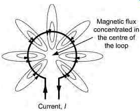
FIG. 5 Magnetic field
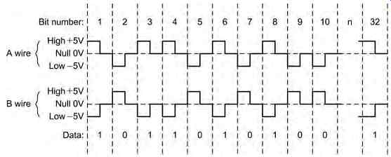
FIG. 6 Digital signal
Typical applications of signals transmitted down a twisted-pair of wires include Arinc 429 signals as illustrated in FIG. 6. Any other system wires adjacent to this pair will be affected by cross-talk.
Two wires (A and B) each carry a 5 volt digital signal arranged as bipolar return to zero (BPRZ). The extent of the cross-talk is equal to the sum of the dig ital signals; if this sum is zero (or nearly zero) then the affects of cross-talk are eliminated.
Consider three wires in a cable as illustrated in FIG. 7. Wires A and B are formed as a twisted pair carrying a digital signal. If the signal sent through wire A is 10 volts with respect to wire B (a reference voltage of zero) then wire C wire picks up cross talk noise. If the digital signals are arranged as per the second illustration, the opposite polarity signal of 5 volts on wires A and B cancel each other out, the cross-talk effect wire C is eliminated.
Key maintenance point
Twisting wires together also provides a neater installation; the number of twists per given length should be specified in order to achieve the desired EMI protection.
Key maintenance point
In some installations, further EMI protection is given by the addition of shielding over the twisted pair of wires.
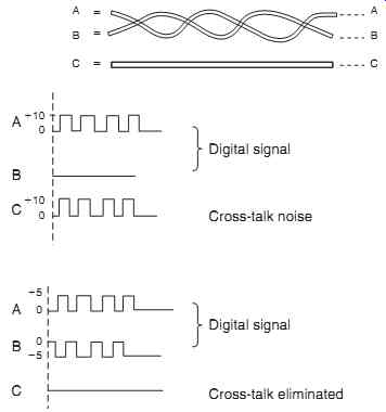
FIG. 7 Twisted pairs and cross talk -- Cross-talk eliminated
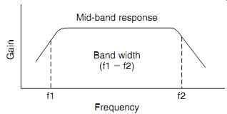
FIG. 8 Bandwidth
1.4 Bandwidth
Bandwidth is the difference between the upper and lower cut-off frequencies of analogue amplifying circuits; the unit of bandwidth is hertz (Hz). The characteristics of bandwidth is illustrated in FIG. 8. This is a central concept in electronics, radio frequency (RF) systems and signal processing. It also has to be considered in the context of EMI; high frequencies should be filtered out of a circuit wherever possible, without compromising its functionality.
In computers, digital bandwidth refers to the rate at which data is transmitted/received; this is measured in bits per second (BPS). A digital communication network has a given bandwidth in terms of its overall channel capacity and throughput (consumption). Channel capacity (in BPS) is proportional to the analog bandwidth in hertz (Hz); this is the maximum amount of error-free digital data that can be transmit ted via a communication link with a specified band width in the presence of EMI. The deeper theory associated with this subject is beyond the scope of this guide; students wishing to research this subject in more detail should refer to the Shannon-Hartley theorem
Test your understanding
Why do higher-frequency signals lead to increased cross-talk?
Test your understanding
How does twisting pairs of wiring reduce cross-talk?
1.5 Radiated EMI
There are many sources of EMI throughout the air craft. Those sources known to radiate EMI include:
-- fluorescent lights
-- radio and radar transmitters
-- power lines
-- AC powered window heat controllers
-- motors/generators
-- switching and light dimming circuits
-- microprocessors
-- pulsed high-frequency circuits
-- data bus cables (but not fiber optic cables)
-- static discharge and lightning
The energy generated by these sources is radiated as an electromagnetic field. From first principles, we know that the coupling only takes place when there is a relative movement of electromagnet field and conductor; digital circuits are (by definition) switching currents on/off with fast and short pulse rise/fall times. Unless adequate precautions are taken to eliminate the interference at source and/or to reduce the equipment's radiation of EMI, the energy can then become coupled into other circuits. In electromagnetic field radiation, energy is transmitted through electrically nonconductive paths, such as air, plastic materials, or fiberglass.
1.6 EMI susceptibility
There are many systems on the aircraft that which may be susceptible to electromagnetic interference.
These include:
-- radio and radar receivers
-- microprocessors and other microelectronic systems
-- electronic instruments
-- control systems
-- audio and in-flight entertainment systems ( IFE)
Whether a system will have an adverse response to electromagnetic interference depends on the type and amount of emitted energy in conjunction with the susceptibility threshold of the receiving system. The threshold of susceptibility is the minimum interference signal level (conducted or radiated) that results in equipment performance that is indistinguishable from the normal operation. If the threshold is exceeded then the performance of the equipment will become degraded. Note that, when the susceptibility threshold level is greater than the levels of radiated emissions, electromagnetic interference problems do not exist.
Systems to which this applies have electromagnetic compatibility (EMC). In other words, the systems will operate as intended and any EMI generated is at such a level that it does not affect normal operation.
2. EMI reduction
Planning for electromagnetic compatibility must be initiated in the design phase of a device or system. If this is not satisfactorily addressed, interference problems may arise. The three factors necessary to produce an EMI problem are:
-- source(s) of interference (sometimes called noise)
-- a means of coupling (by conduction or radiation)
-- susceptible components or circuits
To reduce the effects of EMI, or electrical noise, at least one of these factors must be addressed. The following lists some techniques used for EMI reduction to tackle these three factors (note that some techniques address more than one factor).
1. Suppress the interference at source
-- Enclose the interference source(s) in a screened metal enclosure and then ensure that the enclosure is adequately grounded
-- Use transient suppression on relays, switches and contactors
-- Twist and/or shield bus wires and data bus connections
-- Use screened (i.e. coaxial) cables for audio and radio-frequency signals
-- Keep pulse rise times as slow and long as possible
-- Check that enclosures, racks and other supporting structures are grounded effectively.
2. Reduce noise coupling
-- Separate power leads from interconnecting signal wires
-- Twist and/or shield noisy wires and data bus connections
-- Use screened (i.e. coaxial) cables for audio and radio-frequency signals
-- Keep ground leads as short as possible
-- Pay close attention to potential ground loops
-- Filter noisy output leads
-- Physically relocate receivers and sensitive equipment away from interference sources.
3. Increase the susceptibility thresholds
-- Limit the bandwidth of circuits wherever possible
-- Limit the gain and sensitivity of circuits wherever possible
-- Ensure that enclosures are grounded and that internal screens are fitted
-- Fit components that are inherently less susceptible to the effect of stray radiated fields.
3. High-intensity/energy radiated fields
High-intensity/energy radiated fields (HIRF/HERF) are generated by certain radio-frequency (RF) sources that are external to the aircraft. These fields disrupt electronic components and systems within the aircraft via currents that are induced from these fields into the aircraft's wiring. (The terms HIRF and HERF mean the same thing; HIRF will be used for the remainder of this section.) Radio, radar and television transmitters (particularly highly directional broadcasts) have the capability of adversely affecting the operation of aircraft electrical and electronic systems. The HIRF environment has become a significant threat to aircraft using the electronic systems described in this guide, together with the communications, navigation and flight guidance systems. These systems are potentially very susceptible to the HIRF environment. Accidents and incidents on aircraft with such systems have led to the need for a thorough understanding of, and increased protection from, high-intensity radiated fields.
Practical experience with the effects of HIRF often result in unexplained and unrelated disruption to air craft systems e.g. simultaneous navigation errors and erroneous engine indications. These systems then start operating normally again without being attributed to any specific equipment failures. HIRF has been cited as the cause of misleading roll and pitch information on electronic displays and the total loss of engine power due to interference with electronic control systems. The need for protection of modern electrical and electronic systems from HIRF is required because of the:
-- dependence on these systems used for the continued safe flight and landing of the aircraft
-- increased use of composite materials (reducing the natural Faraday cage protection of metallic structures)
-- Increased complexity of digital systems (faster operating speeds, higher-density integrated circuits)
-- expanded frequency usage of microwave energy
-- increased quantity and power of transmitters
-- proliferation of RF transmitters.
3.1 HIRF environment
The HIRF environment is created by the transmission of high-power radio-frequency (RF) energy into free space. These transmissions can be from military systems, television, radio, radars and satellites communicating with ground-based equipment, ships or other aircraft. When an aircraft operates in a HIRF environment, this can have an adverse effect on the aircraft systems and equipment that could result in system failure, malfunction, or misleading information. The process whereby electromagnetic energy from an RF source is induced in a system by radiation is termed coupling. It is entirely possible that HIRF will affect individual components through to system level via individual wires (or wire bundles) that connect the items of equipment. In the event of the HIRF environment having an adverse effect on systems, it is essential that the aircraft has the capability for continued controlled flight and landing to a suitable location, albeit under emergency conditions.
3.2 HIRF characteristics
The analysis of HIRF is centered on the frequency of transmission and field strength. The practical considerations of RF transmissions are from approximately 10 kilohertz (10 kHz) through to 100 gigahertz (100 GHz). Field strength is defined as the magnitude of the electromagnetic energy propagating in free space expressed in volts per meter (V/m). Aircraft systems need to be tested and/or analyzed across a range of frequencies and field strengths to determine their susceptibility characteristics. Certain systems (or individual items of equipment) are immune to HIRF and have the ability to continue to perform their intended function. This could occur as an inherent or system design feature of the equipment, e.g. if it is located behind a material (reflection plane) that reflects RF signals.
Alternatively, a decrease in electromagnetic field strength in transmission from one point to another can occur by attenuation, expressed in decibels (dB). Attenuation is the scalar ratio of the RF energy input magnitude and output magnitude. (Further details of attenuation are given in the appendices.). In the HIRF environment, the ratio of current induced in a wire bundle form the external HIRF field strength (as a function of frequency) is termed the transfer function. An item of equipment or system that is susceptible to the HIRF environment means that it is unable to perform its intended function; this will be defined by a susceptibility level, where the effects of interference from HIRF become apparent.