AMAZON multi-meters discounts AMAZON oscilloscope discounts
One of the fundamental electrical/electronic systems associated with the aircraft industry is the crash survivable flight data recorder (FDR). This is often referred to in the press as the 'black box‘, even though the item is painted bright orange! Flight data recorders used for accident investigation are mandatory items of equipment in commercial transport aircraft. Efforts to introduce crash-survivable flight data recorders can be traced back to the 1940s; the FDR has now been supplemented with the cockpit voice recorder (CVR). Recorders are used after an incident or accident as an integral part of the investigators' efforts to establish the cause(s).
Data recorders can also be used to indicate trends in aircraft and engine performance. Algorithms are established for healthy and normal conditions during the aircraft's flight-testing program and the early period of service. These algorithms include engine parameters such as engine exhaust temperature, oil pressure and shaft vibration for given speeds and altitudes. These parameters are then monitored during the aircraft's life; any deviations from the norm are analyzed to determine if the engine requires inspection, maintenance or removal. This section reviews the range of FDR/CVR technologies that are employed for both accident investigation and trend monitoring.
1. Flight data recorder history
A series of fatal accidents involving the De Havilland DH106 Comet in 1953 and 1954 led to the grounding of the entire Comet fleet pending an investigation. There were no survivors or witnesses to these accidents and an exhaustive investigation at the Royal Aircraft Establishment at Farnborough, UK, eventually concluded that metal fatigue was the primary cause of the accidents. One of the ideas that came out of these investigations was for the development of a crash-survivable device to record the flight crew's conversations and other aircraft data. Doctor David Warren of the Aeronautical Research Laboratories of Melbourne, Australia, was on one of the investigation committees; he concluded that such recorders would be of tremendous benefit in determining the likely cause(s) of an accident. The idea was that design improvements and/or operating procedures would be introduced to eliminate avoidable accidents from the same cause. The proposed recorder would have to survive both the high g forces and the potential fire resulting from an aircraft crash; the technology required for such a device did not become available until 1958.
Key point
Flight data recorders (FDR) are often referred to in the press as the 'black box ', even though the item is painted bright orange.
Test your understanding 1
Describe how data recorders can also be used to indicate trends in aircraft and engine performance.
1.1 Scratch foil
The technology used in first-generation flight data recorders was based on a roll of steel foil tape embossed with five separate items of recorded data (parameters), see FIG. 1; these parameters were:
-- heading
-- altitude
-- air speed
-- vertical acceleration
-- time
The foil is made from a high nickel content steel; several hundred feet of foil, approximately 125 mm wide, is rolled onto a spool. When the recorder is switched on, the foil is transferred from a feed spool onto the take-up spool after passing under five recording needles (hardened or diamond-tipped styli) that move across the foil in response to their respective inputs. With the foil tape removed from the recorder, the various traces (FIG. 2) are compared with a transparent overlay with markings to measure the recorded parameters.
This early 'scratched-foil' technology gave the investigators more data than had been previously avail able; however, it was soon realized that five parameters did not provide sufficient data for meaningful accident investigation.
1.2 Magnetic recording
Second-generation recorders were introduced onto aircraft during the 1960s based on one of two recording media; steel wire or magnetic tape. When the recorder is switched on, the wire is transferred onto another drum after passing over record/replay heads.
Steel wire recording technology was used by the telegraphy industry from the late 1890s; it was subsequently developed for other industrial applications and home entertainment until the introduction of magnetic tape recorders in the late 1940s. Even with very fine diameter of approximately 100 micrometers, steel wire is intrinsically more crash-survivable than magnetic tape, and this medium was used for recording analog data from the 1950s through to the 1970s. Wire recorders have a high media density; this is made possible by the solid metal medium and relatively fast speed (typically 24 inches per second) over the record/replay heads. One hour of recorded data could be achieved with approximately 7000 feet of wire wound onto a three-inch-diameter drum.
The technology required to protect magnetic wire or tape was eventually developed; the first application of magnetic tape recorders was to record the last thirty minutes of crew voice communications and noise within the flight compartment environment. The cock pit voice recorder (CVR) required substantial packaging to enable it to be crash-survivable. This magnetic tape technology (recording data in a digital format) was then applied to FDR applications. This third generation FDR facilitated the recording of many more flight parameters from the airframe and engines while meeting higher crash and fire protection requirements.
Inside the write head is a small coil; when voltages are applied to the coil, an electromagnetic field is created; particles in the wire or tape are aligned on a micro level with the field as it passes over the head.
=========
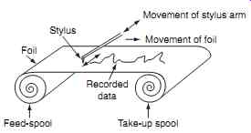
FIG. 1 Scratched foil recorder principles.
Foil Stylus Movement of stylus arm Movement of foil Recorded data Take-up spool Feed-spool
==========
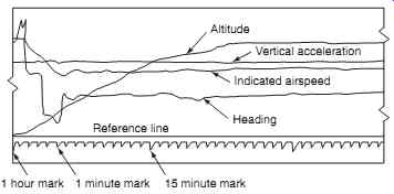
FIG. 2 Scratched foil recorded data
Altitude Vertical acceleration Indicated airspeed Heading Reference line 1 hour mark 1 minute mark 15 minute mark
===========
To analyze electromagnetic recorded tape, an electronic process is required such that digitally coded data can be converted back (decoded) into its analogue form required for presentation and/or display purposes. To read the data stored on the wire/tape, it is passed over a reading head; this is similar in physical construction to the writing head. As each section of wire or tape passes over the head, the particles are aligned in specific directions, inducing small voltages into the coil. The polarity of the voltages indicates whether a binary one or zero is stored. The voltage signals are processed electronically to produce analogue signals for use in displays or charts.
1.3 Solid state data recorders
Solid-state digital flight data recorder (DFDR) technology became commercially viable in the 1990s.
Data is stored in semiconductor memory via integrated circuits. Solid-state memory does not require any servicing, maintenance or overhaul. Furthermore, retrieval and interpretation of the data via personal computer-based software is a more efficient process.
Recorders are now also used for reasons other than accident investigation, e.g. to indicate trends in aircraft and engine performance. Algorithms are established for healthy conditions during the aircraft's flight-testing program and the early period of service; these include engine parameters such as oil temperature, oil pressure and shaft vibration for given speeds and altitudes. These parameters are then monitored during the aircraft's life and any deviations from the norm are analyzed to deter mine if the engine requires inspection, maintenance or removal. Low-cost, high-performance, rugged solutions are required for the processing and data recording.
Equipment such as the SSDR product range developed by Specialist Electronics Services (SES) Ltd has many applications in the aerospace and defense industry. The SSDR product range developed and fielded by SES is designed with flexibility and expandability in mind.
The SSDR-F is a panel-mounted data recorder providing a recording solution where space and mass are at a premium. It is specified where access to the removable media is required from within the flight compartment. The unit features a high-speed recording function that is able to write data to a removable solid state memory module from multiple monitored interfaces at speeds up to 35 Mbits per second (MBPS). Memory modules are available in many sizes up to 16 GBytes. A Pentium compatible processor, allowing application specific data gathering regimes to be accommodated, provides processing functions.
The Solid State Data Recorder-Expandable (SSDR-E) is a high-speed, high-capacity expandable data recorder with extensive data acquisition and communications flexibility. The recorder is built from the concept of multiple recording, data acquisition and communication modules that are assembled together to provide a system that meets the specific bespoke requirements of a customer application.
The recorder contains a master processor module which provides control and configuration of any other modules contained in the system. This master processor provides a high-performance general purpose processor that controls all other data acquisition, recording and communication modules. The processor module also provides multiple high-speed USB 2.0, Giga Ethernet and VGA interfaces.
The baseline S3DR-E recorder is built from a master processor combined with a recording module and an integrated power supply. Alternative recorder con-
figurations can be built from any combination of up to seven data acquisition, communications and recording modules. Each recording module can be built from either a dual PCMCIA recorder with a dedicated I/O processor, or a high-capacity (100 byte), high-speed (up to 480 MBPS) dedicated recording module.
2. Mandatory equipment requirements
In the late 1960s, the UK Civil Aviation Authority (CAA) stipulated a need for additional parameters to be recorded; FDRs using scratched foil were developed to mark both sides of the foil. This allowed for the recording of additional parameters, e.g. pitch, roll and flap position. Although this provided additional information for the accident investigator, it increased the complexity of the recorder resulting in lower reliability. Furthermore, the additional information contained on the scratch-foil was becoming harder to read and required high skill levels to interpret the data.
Larger, more complex aircraft were introduced in the 1960/70s. These aircraft were flying faster, higher and farther than had been previously possible. They had reduced flight crew; the navigator and wireless operators were being replaced by computerized (albeit analogue) avionics bringing reduced operating costs.
High-density passenger operations, reduced flight crew and longer flights were becoming the norm. This created new problems for the accident investigators; more data was required to identify the probable cause of an accident. Flight data acquisition units (FDAU) were introduced to provide an interface between air craft systems and the FDR. The FDAU collects, or acquires, a variety of analogue signals from around the aircraft, converts them into a single digital data stream to the recorder. In the late 1970s and early 1980s the digital flight data recorder (DFDR) could record 32 parameters for a 25 hour period. (This represented the round-trip time between cities in the USA, Europe and Asia.)
Key point
The FDAU collects, or acquires, a variety of analog signals and converts them into a digital data stream to the recorder.
The specific parameters to be recorded are stipulated by the regulatory authorities. In Europe, commercial air transport (fixed wing and rotary wing) aircraft are regulated under JAR OPS 1 and 3 respectively.
For flight data recorders, these regulations take into account when the aircraft was first issued with an individual Certificate of Airworthiness. Aircraft operating under JAR OPS 1 are required to install a dig ital flight data recorder (DFDR). The DFDR has to be able to retain the recorded data for a minimum of the last 25 hours of its operation (10 hours for aircraft below 5700 kg maximum take of mass). The flight data recorder must start to record data automatically prior to the aircraft being capable of moving under its own power. The recorder must stop automatically after the aircraft is incapable of moving under its own power.
The flight data recorder must have a device to assist with locating that recorder if it is submerged in water.
The mandatory parameters required for an aircraft depend on the size of the aircraft and the prevailing regulatory rules applied to that aircraft. The mandatory parameters required for multi-engine turbine powered with maximum approved seating configuration for more than nine passengers and maximum take-off mass under 27,000 kg are shown in Table 1. (Note that all parameters must be referenced to a timescale or relative time count.)
For aircraft over 27,000 kg maximum take-off mass, additional mandatory requirements are required; these are listed in Table 2. Aircraft with an electronic flight instrument system (EFIS) are required to have the additional parameters listed in Table 3.
Electronic flight instrument system (EFIS) technology was introduced during the 1980s based on the cathode ray tube (CRT); the established technology is now liquid crystal displays (LCD). The attitude director indicator (ADI) and horizontal situation indicator (HSI) are included within a basic EFIS installation; other indications and displays are incorporated through various configurations.
There are some exceptions to the above allowed under JAR OPS 1, that have to be agreed and authorized, e.g. if the required transducer is not available; or if the aircraft system or equipment producing the data needs to be modified; or if the signals are incompatible with the recording system. It is a fundamental requirement that the parameters being recorded are obtained from sources that enable accurate correlation with the information displayed to the flight crew.
Helicopters used for commercial transportation (with maximum certificated take-off mass over 3175 kg) also require a flight data recorder. This must be capable of recording data during at least the last eight hours of its operation; mandatory parameters are shown in Table 4. Helicopters over 7000 kg require the additional parameters shown in Table 5 Table 1 JAR OPS 1 mandatory FDR parameters:
-- Time or relative time count
-- Pressure altitude
-- Indicated airspeed
-- Heading
-- Normal acceleration
-- Pitch attitude
-- Roll attitude
-- Manual radio transmission keying
-- Propulsive thrust/power on each engine and thrust/power lever position (if applicable)
-- Trailing edge flap or cockpit control selection
-- Leading edge flap or cockpit control selection
-- Thrust reverser status
-- Ground spoiler position and/or speed brake selection
-- Total or outside air temperature
-- Autopilot and autothrottle mode and engagement status
-- Longitudinal acceleration (body axis)
-- Lateral acceleration 1
-- Angle of attack 2 1
Lateral acceleration on aircraft with 5700 kg maximum take-off mass.
2
Angle of attack on aircraft with less than 5700 kg maxi mum take-off mass.
Table 2 JAR OPS 1 Mandatory FDR parameters (aircraft over 27,000 kg)
-- Primary flight controls - control surface position and/or pilot input (pitch, roll, yaw)
-- Pitch trim position
-- Radio altitude
-- Vertical beam deviation (ILS glide path or MLS elevation) 1
-- Horizontal beam deviation (coupled approaches: ILS localizer or MLS azimuth)
-- Marker beacon passage
-- Warnings (specified on the aircraft installation)
-- Optional navigation receiver frequency selection
-- Optional DME 2 distance
-- Landing gear squat switch status or air/ground status
-- Terrain awareness warning system (TAWS)
-- Angle of attack
-- Low pressure warning (hydraulic and pneumatic power)
-- Groundspeed
-- Landing gear or gear selector position 1
Instrument landing and microwave landing systems (ILS and MLS) are used for precision approach and landing.
2
Distance measurement equipment (DME) is a short/medium-range navigation system based on secondary radar principles. (These systems are described in a related book in the series: Aircraft Communications and Navigation Systems.)
Table 3 Additional parameters for aircraft with electronic instruments
-- Selected barometric setting
-- Selected altitude
-- Selected speed
-- Selected mach
-- Selected vertical speed
-- Selected heading
-- Selected flight path
-- Selected decision height
-- EFIS display format
-- Multi function/engine/alerts display format
Table 4 Mandatory FDR parameters for commercial transport helicopters (less than 7000 kg)
-- Time or relative time count
-- Pressure altitude
-- Indicated airspeed
-- Heading
-- Normal acceleration
-- Pitch attitude
-- Roll attitude
-- Manual radio transmission keying
-- Power on each engine
-- Engine power control position
-- Main rotor speed
-- Rotor brake (if installed)
-- Primary flight controls
-- Collective pitch
-- Longitudinal cyclic pitch
-- Lateral cyclic pitch
-- Tail rotor pedal
-- Controllable stabilator
-- Hydraulic selection
-- Warnings
-- Outside air temperature
-- Autopilot engagement status
-- Stability augmentation system engagement
Table 5 Additional parameters for helicopters over 7000 kg
-- Main gear box oil pressure
-- Main gear box oil temperature
-- Yaw rate or yaw acceleration
-- Indicated sling load force (if installed)
-- Longitudinal acceleration (body axis)
-- Lateral acceleration
-- Radio altitude
-- Vertical beam deviation (ILS glide path or MLS elevation)
-- Horizontal beam deviation (ILS localizer or MLS azimuth)
-- Marker beacon passage
-- Warnings
-- Optional navigation receiver frequency selection
-- Optional DME distance
-- Optional navigation data
-- Landing gear or gear selector position
Key point
The flight data recorder must stop automatically after the aircraft is incapable of moving under its own power.
Key point
Parameters being recorded are obtained from sources that are accurately correlated with the information displayed to the flight crew.