AMAZON multi-meters discounts AMAZON oscilloscope discounts
(cont. from part 1)
4. Ground proximity modes
4.1 Mode 1: excessive descent rate
Referring to FIG. 8, Mode 1 GPWS detects excessive sink (or descent) rate. The computer will provide a repeated aural alert of 'SINK RATEs‘. This is followed by a repeated aural warning of 'PULL UP' if the excessive descent rate continues, together with illumination of the ground proximity warning light. Amber and red text messages consistent with the aural messages are given on the navigation display.
The computer derives excessive descent rate alert and warning from the following primary inputs:
-- radio altitude
-- vertical speed
-- barometric altitude
There are two envelopes within the TAWS software algorithms. The first envelope provides the 'SINK RATE' caution, if the aircraft flight path continues into the second envelope, the 'PULL UP' warning is produced. Mode 1 is inhibited below a minimum height, typically 30 feet; it is also independent of aircraft configuration, e.g. flaps and/or undercarriage positions.
4.2 Mode 2: excessive terrain closure rate
This mode provides protection in one of two ways (see FIG. 9 ): excessive terrain closure rate with flaps not in landing position (Mode 2A) and excessive terrain closure rate with flaps and gear in the landing position (Mode 2B).
Entering the Mode 2A envelope (see FIG. 10) will cause the repeated ' TERRAIN-TERRAIN ' aural alert to sound. This is followed by the ' PULL UP ' warning if the closure rate is too large. Airspeed schedules further refine the Mode 2A profile.
The height of the Mode 2B envelope floor varies dependent upon barometric descent rate and air speed (FIG. 11). The cautionary voice message is accompanied with an amber text message consistent with the aural message. If the terrain closure rate penetrates the warning zone, an aural 'PULL UP' voice message is produced together with a red text message consistent with the aural message. Mode 2 is inhibited below a minimum terrain clearance, typically 30 feet.
4.3 Mode 3: negative climb rate or altitude loss after take off or go around
During an approach, in the landing configuration, Mode 3 arms when the aircraft descends below a specified altitude as illustrated in FIG. 12. The mode becomes active if either gear or flaps are retracted.
The cautionary alerts are 'DON'T SINK' or 'TOO LOW TERRAIN' (depending on what has been programmed into the computer during installation) together with an amber text message consistent with the aural message. Mode 3 does not have a warning zone; it is inhibited below a minimum terrain clearance and barometric altitude.
===========
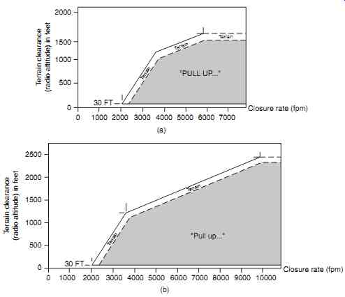
FIG. 10 GPWS Mode 2A envelopes: (a) excessive terrain closure rate (airspeed
220 knots), (b) excessive terrain closure rate (airspeed 220 knots)
==============
4.4 Mode 4: flight into terrain when not in landing configuration
This mode is programmed in one of three ways; see FIG. 13. Mode 4A is for unsafe terrain clearance with flaps in the landing position, but the gear is up; this will initially generate a 'TOO LOW TERRAIN‘. This is followed by a 'TOO LOW GEAR' voice message with an amber text message consistent with the aural message.
Alternatively, if the flaps are up and the gear is down (Mode 4B), the voice message 'TOO LOW FLAPS' is produced. The third condition (Mode 4C) is caused by unsafe terrain clearance after take-off or go around; the will produce a 'TOO LOW TERRAIN' caution. The various envelopes associated with Mode 4 are illustrated in FIG. 14.
4.5 Mode 5: excessive downward deviation from an ILS glide slope
Mode 5 provides protection on the glide slope in both hard and soft alert areas (FIG. 15(a)). This mode becomes active when the number one ILS receiver has a valid signal, gear is down and radio altitude is between the limits shown in FIG. 15(b)
Descent below the glide slope (G/S) causes 'GLIDE SLOPE' voice message and an amber text message. Mode 5 can be inhibited by selecting the GPWS G/S push button switch when below 1000 ft RA. The mode automatically reactivates for a new envelope penetration.
4.6 Mode 6 Altitude callouts
When the aircraft descends to 500 feet above run way elevation, a voice message of 'Five hundred' is given; there are no text messages generated with this Mode. Within Mode 6, some manufactures offer pre determined altitude callouts, see FIG. 16.
This mode can also incorporate other optional features such as bank angle protection, see FIG. 17.
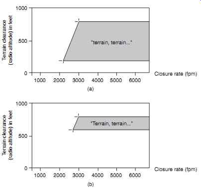
FIG. 11 GPWS Mode 2B envelopes: (a) excessive terrain closure rate - flaps
down (barometric rate 400 f.p.m.), (b) excessive terrain closure rate envelope
- flaps down (barometric rate 1000 f.p.m.) (b)
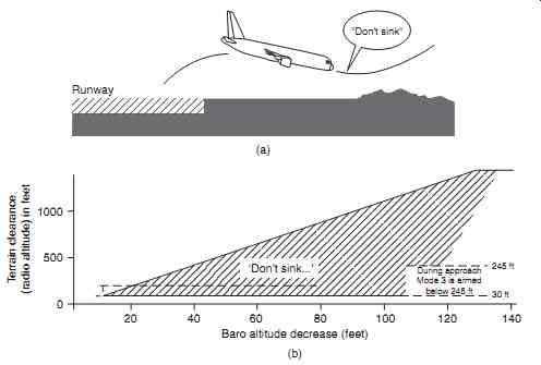
FIG. 12 GPWS Mode 3: (a) altitude loss after take-off profile, (b) altitude
loss after take-off envelope
============
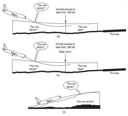
FIG. 13 GPWS Mode 4 profiles: (a) flight into terrain when not in landing
configuration - gear up, (b) flight into terrain when not in landing configuration
- gear down/flaps up, (c) flight into terrain when not in landing configuration
(take-off or go-around)
"Too low terrain" "Too low terrain" "Too low gear" Aircraft slowed to less than 190 kts Runway (a) "Too low terrain" "Too low terrain" "Too low flaps" Aircraft slowed to less than 159 kts Gear down Runway (b) "Too low terrain"
'Too low terrain' (c)
==============
4.7 Mode 7 wind shear
Additional features on larger aircraft include a wind shear functionality within the TAWS computer. This is incorporated as ground proximity Mode 7. Wind shear can occur in both the vertical and horizontal directions; this is particularly hazardous to aircraft during take-off and landing. Specific weather conditions known a microbursts cause short-lived, rapid air movements from clouds towards the ground.
When the air from the microburst reaches the ground it spreads in all directions, this has an effect on the aircraft depending on its relative position to the microburst.
4.7.1 Microburst
Referring to FIG. 18, when approaching the micro burst, it creates an increase in headwind causing a temporary increase of airspeed and lift; if the pilot were unaware of the condition creating the increased air speed; the normal reaction would be to reduce power.
When flying through the microburst, the head wind reduces and the aircraft is subjected to a downdraught. As the aircraft exits the microburst, the downdraught now becomes a tail wind, thereby reducing airspeed and lift. This complete sequence of events happens very quickly, and could lead to a sudden loss of airspeed and altitude. In the take-off and climb-out phase of flight, an aircraft is flying just above stall speed; wind shear is a severe threat.
During approach and landing, engine thrust will be low; if a microburst is encountered, the crew will have to react very quickly to recognize and compensate for these conditions.

FIG. 14 GPWS Mode 4 envelopes: (a) flight into terrain when not in landing
configuration - gear up, (b) flight into terrain when not in landing configuration
- gear down/flaps up, (c) flight into terrain when not in landing configuration
(take-off or go-around)
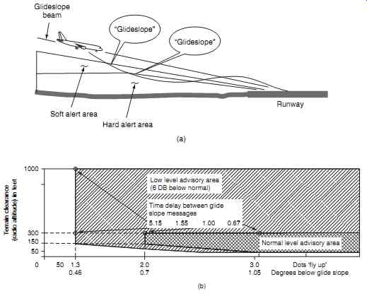
FIG. 15 GPWS Mode 5: (a) excessive downward deviation from an ILS glide slope
profile, (b) excessive downward deviation from an ILS glide slope envelope
4.7.2 Doppler radar
Modern weather radar systems are able to detect the horizontal movement of droplets using Doppler shift techniques. Doppler is usually associated with self-contained navigation systems. (This subject is described further in Aircraft Communications and Navigation Systems.) The Doppler effect can be summarized here as: ' the frequency of a wave apparently changes as its source moves closer to, or farther away from an observer'. This feature allows wind shear created by microbursts to be detected. Referring to FIG. 19, the microwave energy pulses from the antenna are reflected by the water droplets as in the conventional weather radar system.
Using the Doppler shift principle, the frequency of energy pulse returned by droplets (B) moving towards the aircraft will be at a higher frequency than the transmitted frequency. The frequency of energy pulse returned by droplets moving away from the aircraft (A) will be at a lower frequency than the transmitted frequency. These Doppler shifts are used to determine the direction and velocity of the air movement resulting from a microburst.
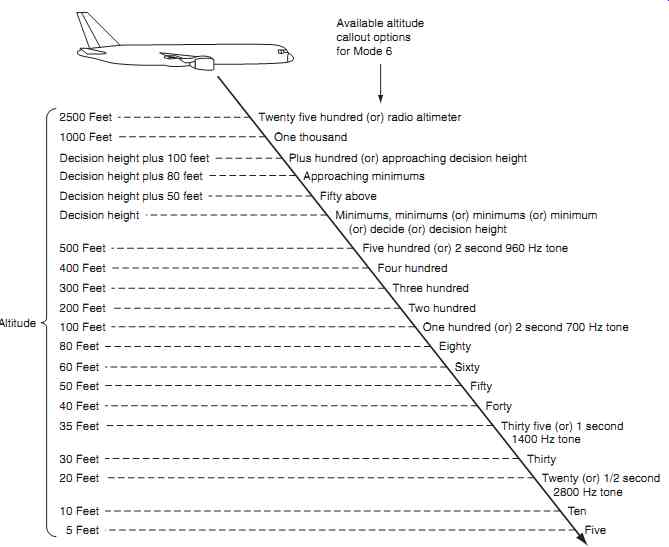
FIG. 16 GPWS Mode 6 altitude callouts
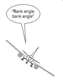
FIG. 17 GPWS Mode 6 bank angle
4.7.3 Predictive wind shear
Visual and audible warnings of predictive wind shear conditions are provided to the crew. The visual warnings are given on the multi-function or navigation displays using a wind shear icon and message, together with warning lights on the glare shield. Audible warnings are provided as computer generated voice alerts over the cockpit speakers, typically ' WIND SHEAR WIND SHEAR ‘. The system automatically configures itself for the phase of flight; it is normally inhibited below 50 feet radio altitude during take-off and landing. During an approach, Mode 7 is activated below 2500 feet radio altitude and has typical envelope incorporated as illustrated in FIG. 20
Key point
When approaching a microburst, it creates an increase in headwind, causing a temporary increase of airspeed and lift.

FIG. 18 Microbursts
5. Forward-looking terrain avoidance (FLTA)
This TAWS feature uses aircraft position, altitude and flight path information together with details of terrain, obstacles and known runways in the database.
Referring to FIG. 21, the system provides an envelope of protection by comparing the flight path with the details contained in the database. There are two look-ahead distance features; these are functions of terrain clearance floor height and ground speed.
Referring to FIG. 21, alert areas are projected along the flight path in three levels:
-- warning
-- alert
-- caution
=========
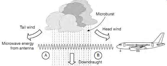
FIG. 19 Doppler radar
Tail wind Microburst Head wind B Downdraught; Doppler frequency shift between A and B indicates a wind shear condition A Microwave energy from antenna
===========

FIG. 20 GPWS Mode 7: (a) wind sheer detection profile, (b) wind sheer detection
envelope (b)
============

FIG. 21 Rotorcraft autorotation: (a) normal powered flight, (b) autorotation
============
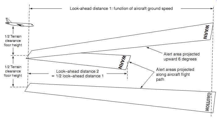
FIG. 22 FLTA flight path
Look-ahead distance 1: function of aircraft ground speed Alert area projected upward 6 degrees Alert areas projected along aircraft flight path Look-ahead distance 2 _ 1/2 look-ahead distance 1 1/2 Terrain clearance floor height 1/2 Terrain clearance floor height WARN WARN
============
When a runway has been selected in the navigation system, a terrain clearance profile comes into effect as shown in FIG. 22. This profile take into account distance to the runway and height above ground level.
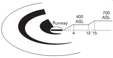
FIG. 23 FLTA runway
===========
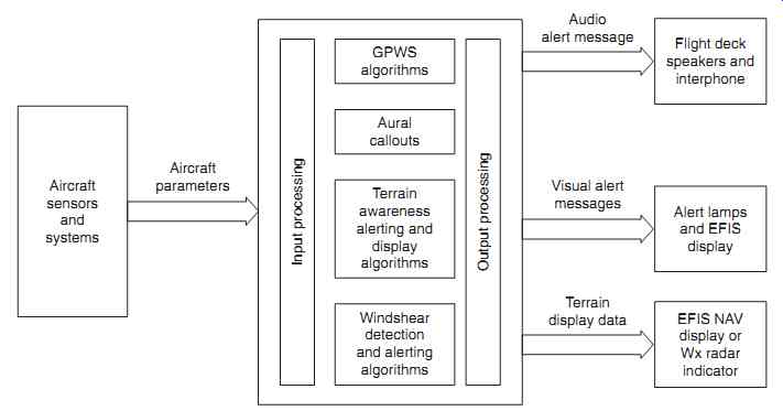
FIG. 24 TAWS architecture
Aircraft sensors and systems Aircraft parameters Audio alert message Visual alert messages Terrain display data GPWS algorithms Flight deck speakers and interphone Alert lamps and EFIS display EFIS NAV display or Wx radar indicator Aural callouts Terrain awareness alerting and display algorithms Windshear detection and alerting algorithms Input processing Output processing
===========
6. Rotorcraft TAWS
Rotorcraft, or helicopters, require additional TAWS considerations as result of their unique flying characteristics and operational roles. In addition to the functions already described, systems installed into rotorcraft need to include:
-- excessive bank angle protection
-- tail strike protection
-- autorotation
During autorotation, the relative upward airflow causes the main rotor blades to rotate at their normal speed; the blades are 'gliding 'in their rotational plane, see FIG. 23. Autorotation facilitates a con trolled descent through to an emergency landing in case of power plant failure; this flight regime has to be recognized by TAWS.
Many national aviation authorities including the FAA and CAA recommend the use of TAWS in helicopters performing specialized roles, e.g. emergency medical services and oil-pipe inspections these often involve low-level operations at night or in low visibility.
7. Architecture and configurations
Typical Class A system architecture is illustrated in FIG. 24. Larger aircraft require TAWS Class A, smaller aircraft require TAWS Class B; this is reflected in the complexity (hence cost) of the hard ware and certification requirements. The various TAWS configurations also take into account the type of interfaces that TAWS requires, e.g. whether the existing aircraft sensors are digital or analogue.
Smaller general aviation aircraft are adopting a simple terrain only feature. This is normally a sub feature of a GPS navigation system, referred to as Class C TAWS. Typical features include:
-- terrain data base
-- terrain elevations relative to the aircraft
-- visual alerting
-- reduced terrain clearance avoidance
-- imminent terrain impact avoidance
-- premature descent alert.
8. Future developments
TAWS is specified in transport category aircraft as a result of mandatory rulemaking. Two main categories of general aviation (GA) aircraft are not included in these rules, however: non-turbine, fixed-wing aircraft (particularly privately owned aircraft), and rotorcraft.
Both of these categories fall under the voluntary Class C TAWS arrangement. Although there are no firm indications of general aviation's adoption of Class C TAWS equipment, the functionality is often included within existing equipment, and many aircraft owners would prefer some level of protection.
Some manufactures are developing an assisted recovery concept, where the aircraft's automatic
flight control system automatically performs the pull up maneuver following a TAWS alert. The system could also steer the aircraft away from prohibited air space for security purposes.
Performance-based systems are being developed that utilize data from an active aircraft database that stores the aircraft's performance characteristics under varying conditions of engine thrust, aircraft weight, altitude, temperature and other inputs. When a TAWS 'PULL UP' warning is given, the system determines if the air craft can actually climb at the required rate to avoid impacting the terrain ahead. If the system predicts that this is not possible, the crew receive an 'AVOID TERRAIN' command, and the system indicates an alternate maneuver to fly the aircraft into safer areas.
To minimize nuisance warnings, the system limits its look-ahead terrain search profile to a narrow sector either side of the aircraft's projected track.
Terrain advisory lines are indicated on a wider scan either side of the projected track to visually alert the crew of potential obstructions. When a terrain avoidance maneuver is initiated, the system switches to a wider scanning sector and anticipates the rate of turn while searching the terrain ahead on a from the original track. Terrain that the aircraft can safely climb over is then depicted with appropriate graphics on the navigation display.
The ground collision avoidance module (GCAM) is a predictive alerting technique derived from a terrain-following/terrain-avoidance system used by military aircraft. GCAM uses a collision prediction and alerting (CPA) function that combines terrain and airport databases with a Model of the aircraft's climb capability. The CPA function predicts potential terrain conflicts from the terrain environment and the air craft's predicted flight path.
The former correlates precise aircraft position information from the GPS and/or other navigation sources with the digital database. The flight path prediction uses current aircraft flight path data to project the flight path more than 2 minutes ahead of the aircraft, and provides visual cautions up to 4 minutes ahead. Alerts are generated when the CPA system predicts the flight path could intersect the terrain, providing terrain avoidance rather than just a warning.
9. QUIZ-- Multiple choice questions
1. A terrain awareness display is only required for:
(a) Class A TAWS
(b) Class-B TAWS
(c) GPWS.
2. Mode 1 terrain awareness cautions are given for:
(a) negative climb rate or altitude loss after take-off
(b) excessive descent rate
(c) altitude callout at 500 feet.
3. When approaching a microburst, it creates:
(a) a decrease in headwind causing a temporary increase of airspeed and lift
(b) an increase in headwind causing a temporary decrease of airspeed and lift
(c) an increase in headwind causing a temporary increase of airspeed and lift.
4. Warning alerts are given for a terrain threat that requires:
(a) immediate crew awareness
(b) confirmation with air traffic control
(c) immediate crew action.
5. Forward-looking terrain avoidance (FLTA) looks:
(a) ahead of and below the aircraft's lateral and vertical flight path
(b) ahead of and above the aircraft's lateral and vertical flight path
(c) either side of and below the aircraft's lateral and vertical flight path.
6. Premature descent alert compares the aircraft's:
(a) ground speed with the proximity of the nearest airport
(b) lateral and vertical position with the proximity of the nearest airport
(c) lateral and vertical position with the proximity of high terrain.
7. Red areas are used on TAWS displays to indicate terrain that is:
(a) above the aircraft's current altitude
(b) level with the aircraft's current altitude
(c) safe in terms of required terrain clearance.
8. The low range radio altimeter (LRRA) is a:
(a) self-contained vertically directed primary radar system
(b) self-contained horizontally directed primary radar system
(c) self-contained vertically directed secondary radar system.
9. Mode 7 (wind shear) is normally inhibited:
(a) above 50 feet radio altitude during take-off and landing
(b) below 50 feet radio altitude during take-off and landing
(c) during take-off and landing.
10. The TAWS computer function creates a four dimensional situation comprising:
(a) latitude, longitude, heading and time
(b) latitude, speed, altitude and time
(c) latitude, longitude, altitude and time.
11. Referring to Fig. 25, this illustrates a:
(a) FLTA profile
(b) GPWS Mode 2 profile
(c) GPWS Mode 1 profile.
12. Referring to FIG. 26, this illustrates a:
(a) GPWS Mode 6 caution
(b) GPWS Mode 3 caution
(c) GPWS Mode 1 warning.
13. Referring to Fig. 27, this is the warning envelope for:
(a) GPWS Mode 5
(b) GPWS Mode 2
(c) GPWS Mode 1.
14. GPWS Mode 3 is defined as:
(a) Excessive terrain closure rate
(b) Negative climb rate, or altitude loss after take off or go around
(c) excessive descent below the glide slope
15. Flight into terrain whilst not in the landing configuration is GPWS Mode:
(a) one
(b) three
(c) four