AMAZON multi-meters discounts AMAZON oscilloscope discounts
Goals:
- • Identify terminal markings for a DC compound motor and a counter emf controller.
- • Describe the operation of a counter emf controller.
- • State the purpose of a relay connected across the armature of a counter emf controller.
- • Connect DC motors and counter emf controllers.
- • Recommend troubleshooting solutions for problems with counter emf controllers.
- • Describe how a definite timer is used to provide time-limit acceleration.
- • Describe the use and operating sequence of a field accelerating relay.
- • Describe the use and operating sequence of a field failure relay.
COMPENSATING TIME ACCELERATION
This type of controller automatically adjusts the starting time intervals, depending on the load connected to the motor. E.g., be cause a heavy load has more inertia for the motor to overcome, a longer time is required to build up the counter emf. Thus, a longer starting period is required. The following starter is an example.
COUNTER EMF CONTROLLER
When a DC motor starts, the generated counter emf across the armature is low. As the motor accelerates, the counter emf increases.
When the voltage across the motor armature reaches a certain value, a relay is actuated to reduce the starting resistance at the right time.
ill. 1 shows the schematic connection diagram for a DC motor controller, using the principle of counter emf acceleration. When the start button is pressed, contactor M is energized and the main contact (M) is closed. The current path is then complete from L1 through the resistor (R1-R2), the armature (A1-A2), and the series field (S1-S2) to L2.
To prevent the contactor from opening, the maintaining contact (M) is operated from the coil (M). This means that a shunt is placed around the start button. When the start button is released, M remains energized through the maintaining contacts (M) until the stop button is pressed.
There is a high voltage drop across R1-R2, but a counter emf isn't present across the armature. As the motor accelerates, the current is reduced. When the counter emf across the armature reaches a value equal to a certain percentage of the full value, relay A (connected across the armature) closes contact A. Thus, resistor R1-R2 is removed from the circuit and the motor is placed directly on the line.
VOLTAGE-SENSITIVE RELAY
The relay (A) is a voltage-sensitive relay, ill. 2. It is commonly used to sense the DC motor armature voltage. This voltage is an indication of motor speed. The voltage-sensitive relay is frequently used in the following applications: hoist controllers; reversing plugging to stop; and applying armature shunt contactors on multistep slowdown and acceleration circuits. Because the relay is adjustable for pickup and dropout, one of its many uses is to control multisteps of acceleration as a motor starter. ill. 1 shows one relay and one resistor for one step of acceleration. For heavier motors and loads, additional relays and resistors can be added to increase the points of acceleration. The additional relays must be adjusted to ensure that the resistances will be cut out of the circuit at the proper times as the motor accelerates.
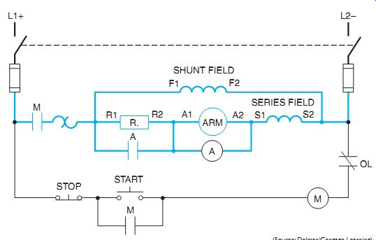
ill. 1 Line diagram of a counter emf controller.
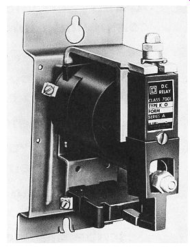
ill. 2 DC voltage sensitive relay for DC motor armature voltages.
FIELD ACCELERATING RELAY
A field accelerating relay, or a full field relay, ill. 3, is used with starters to control adjustable speed motors. This type of relay pro vides the full field during the starting period and limits the armature current during sudden speed changes. The coil of the field accelerating relay is connected in series with the motor armature. When there is a current inrush at startup, or when a sudden speed increase causes excessive armature currents, the coil closes the relay contacts. The closed contacts bypass the shunt field rheostat. The full shunt field strength is provided on starting and excessive armature currents are prevented during speed changes.
FIELD FAILURE RELAY
A field failure relay is a single-pole control relay, ill. 3. The contacts of the relay are connected in the control circuit of the main contactor. The coil is connected in series with the shunt field. If the shunt field fails, the relay coil is de-energized and the relay contact opens the circuit to the motor starter, disconnecting the motor from the line. The field failure relay is a safety feature that can be added to a starter to prevent the motor from greatly increasing its speed if the field is opened accidentally.
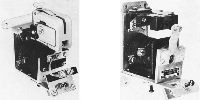
ill. 3 DC field accelerating relay (left) and DC field failure relay (right).
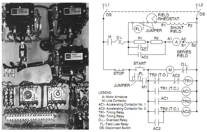
ill. 4 DC reduced voltage magnetic starter and schematic diagram.
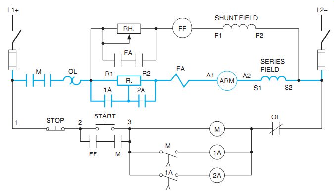
ill. 5 Schematic diagram for definite time limit starting using timing relays,
field accelerating relays, and field failure relays.
LEGEND:
A- Motor Armature; M- Line Contactor AC1- Accelerating Contactor No. 1 AC2- Accelerating Contactor No. 2 TR1- Timing Relay TR2- Timing Relay O.L.- Overload Relay; FL- Field Loss Relay; DS- Disconnect Switch
DEFINITE TIME CONTROL STARTING
A timing relay provides a definite timed interval, which is used to control acceleration while a motor is being brought up to speed. The acceleration steps are controlled by resistors inserted in the line ahead of the motor. The definite time limit acceleration provided by the timing relays means that the resistors remain in the line for a fixed time period before the motor is connected across the line. A typical DC reduced voltage magnetic starter (less enclosure) using timing relays is shown in ill. 4. A schematic for this starter is also shown.
Time limit acceleration is preferred for some applications. Other methods of acceleration (compensating time, counter emf, and current limiting) have the disadvantage that the motor might not accelerate enough to close the running contactor that bypasses the resistors. In other words, the resistors might remain in the circuit and could burn out. This hazard is eliminated by the use of time limit acceleration, because the running contactor is closed automatically after a definite time interval.
As shown in the typical schematic in ill. 5, the closing of the start button energizes coil M. This coil, in turn, instantaneously closes the heavy power contacts (M). The motor is then started through the starting resistor.
The double-break contacts (M) are used to minimize the DC arc. The shunt field and field failure relay (FF) are energized at this same moment. The control contacts (FF and M) close and maintain the circuit across the start button.
The series coil of the field accelerating relay (FA) receives the maximum current flow and closes contacts FA to shunt the circuit across the shunt field rheostat. Because the maximum field strength is present, there is more counter emf and excessive armature currents are prevented.
Main contactor M also activates a normally open, delay-in-closing contact (M). At the end of the time delay of the timing cycle, it energizes the first accelerating relay (1A). Power contact 1A cuts out one step of resistance and also activates the preset timing cycle (1A). The normally open, delay-in-closing contact (1A) energizes the second accelerating relay (2A). This action places the armature across the line. Time limit controllers can be used with series, shunt, or compound wound DC motors. These controllers can drive pumps, fans, compressors, and other classes of machinery when the load varies over a wide range and when automatic or remote control is desired.
QUIZ
1. Why is this type of controller called a counter emf controller?
2. What physical characteristic distinguishes between a main contactor and a relay?
3. Draw an elementary diagram with three points of acceleration.
4. What protection is available from excessive starting currents in the event the timing relays cut out the starting resistors too rapidly for the connected load?
5. How does a field accelerating relay prevent current excess that may occur because of adjusting the rheostat to change speeds?
6. How do individual timers, which have only light, single-pole control contacts, control the acceleration steps of a large DC motor?
7. How may more steps of acceleration be added to a starter?
8. Why is use made of double-break contacts or contacts connected in series such as contacts FA across the rheostat and M in the armature circuit in ill. 4?