AMAZON multi-meters discounts AMAZON oscilloscope discounts
Goals:
- • Describe across-the-line starting for small DC motors.
- • State why a current limiting resistor may be used in the starting circuit for a DC motor.
- • Connect across-the-line starters used with small DC motors.
- • Recommend troubleshooting solutions for across-the-line starters.
- • Draw diagrams for three motor starter control circuits.
Small DC motors can be connected directly across the line for starting because a small amount of friction and inertia is overcome quickly in gaining full speed and developing a counter emf. Fractional horsepower manual starters (discussed in Unit 2) or magnetic contactors and starters (Unit 3) are used for across-the-line starting of small DC motors, ill. 1.
Magnetic across-the-line control of small DC motors is similar to AC control or to two- or three-wire control. Some DC across-the-line starter coils have dual windings because of the added load of multiple break contacts and the fact that the DC circuit lacks the inductive reactance that's present with AC electromagnets. Both windings are used to lift and close the contacts, but only one winding remains in the holding position. The starting (or lifting) winding of the coil is designed for momentary duty only. In ill. 2, assume that coil M is energized momentarily by the start button.
When the starter is closed, it maintains itself through the normally open maintaining contact (M) and the upper winding of the coil because the normally closed contact (M) is now open.
Power contacts M close, and the motor starts across the full-line voltage. The double-break power contacts are designed to minimize the effects of arcing. (DC arcs are greater than those due to AC.) ill. 3 shows another control method used to start a DC motor. In this method, a cur rent-limiting resistor is provided to prevent coil burnout. It is used to limit a continuous duty current flow to some coils or when the coils are overheating.
The coil first receives the maximum current required to close the starter. It then receives the minimum current necessary to hold in the contacts and for continuous duty through the current-limiting resistor.
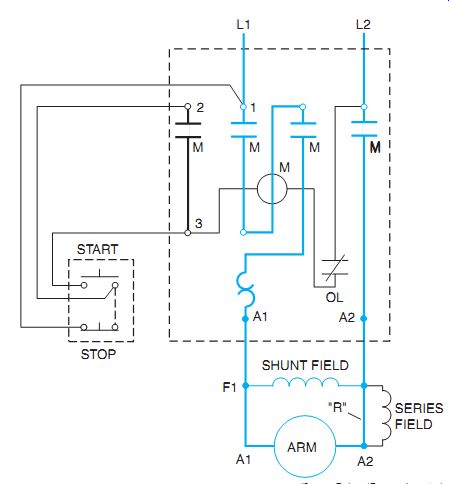
ill. 1 DC full-voltage starter wiring diagram. Connection "R" is
removed with use of series field.
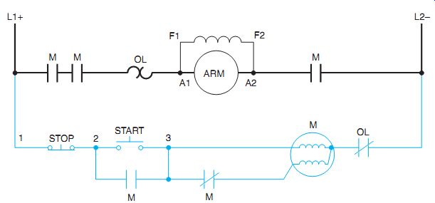
ill. 2 Line diagram of DC motor starter with dual-winding coil.
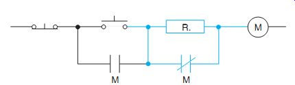
ill. 3 DC starting circuit using current limiting resistor.
QUIZ:
1. Why may small DC motors be started directly across the line?
2. When using a coil that isn't designed for continuous duty, what may happen if a resistor isn't added to the circuit?
3. What is the purpose of a double-break power contact?