AMAZON multi-meters discounts AMAZON oscilloscope discounts
Goals:
• Describe power conversion.
• Tell how solid-state control limits current flow on starting.
• Describe methods of feedback for constant-speed control.
• Discuss armature and field current sensing techniques.
• Describe methods of communicating with controllers.
• Perform maintenance on solid-state DC adjustable speed control.
POWER CONVERSION AND CONTROL
DC motors are widely used in industry be cause of their great versatility. They can be operated at a slow speed with a high torque. They can be run constantly at nameplate speed (base speed) or even above base speed (within safe limits), as shown in ill. 1. It isn't necessary to have a DC power plant and distribution system due to the wide use of solid-state rectifiers. DC is converted at the motor control site from the AC distribution system.
STARTING THE MOTOR
The following factors limit the current flow taken by the armature from the power source:
1. the counter electromotive force (emf)
2. the armature resistance
Because there is no counter emf when the armature is at a standstill, and its resistance is very low, the current taken by the armature on startup will be abnormally high. As a result, the motor armature is gradually fed an increasing amount of voltage, from zero voltage for start, to full voltage for run. A fully energized field is maintained to generate the counter emf required on run to limit the armature current. Counter emf is gradually built up from start, with an in crease in armature speed, to maximum on run.
Motor Speed Control
Motor speed control basics still apply. With full field and armature voltage, the value of revolutions per minute of the motor is the nameplate, or base, speed. When operating the motor below base speed, which is very common, the armature voltage is reduced accordingly.
Full field is maintained.
If it's necessary to operate the motor above base speed, the field voltage is reduced and armature voltage is fully applied. Refer to Graph.
The motor nameplate does not give maximum speed limitations. For a safe operating condition, check with the motor manufacturer for the safe maximum speed limit.
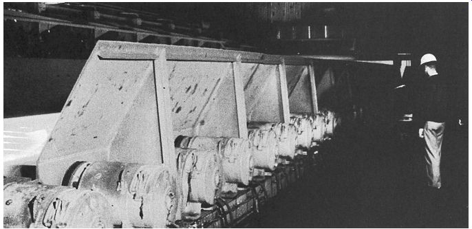
ill. 1 Steelingot being moved by DC compound-wound motors.
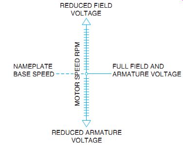
Graph: DC Drive Speed Control.
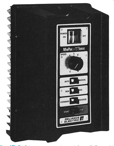
ill. 2 Operator control panel for a DC variable speed control.
DC ADJUSTABLE SPEED CONTROL FROM SINGLE-PHASE AC
A basic DC drive consists of an operator control station that determines when the drive starts and stops. The speed control potentiometer gives a reference signal to the drive controller, as shown in ill. 2.
Smaller size DC motors often operate from a single-phase AC source. Rectified and controlled DC is fed to the armature of the motor by silicon-controlled rectifiers, or thyristors.
This method is similar to the solid-state AC reduced voltage starters shown previously. In this case, however, the SCRs are connected to produce controlled DC from the AC line.
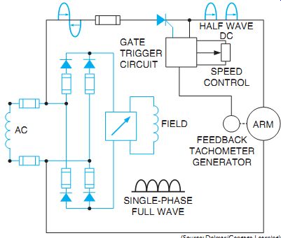
ill. 3 shows a simplified single-phase AC circuit rectified to DC supplying
a DC motor.
The field circuit's a full-wave DC supply (shown graphically) for a greater field strength when required. Motor speed is preset by the operator control. This electronically adjusts for the proper field and armature current strength for the desired speed. The feedback tachometer generator helps to regulate the amount of DC flowing to the armature for high torque, slower than-base speeds. The tachometer generator output voltage is proportional to its speed. The output voltage is connected to the SCR gate control circuit. A change in speed is detected and immediately corrected to maintain a preset constant speed. Generally, DC motors are run at base speed or below.
INSTALLATION AND MAINTENANCE
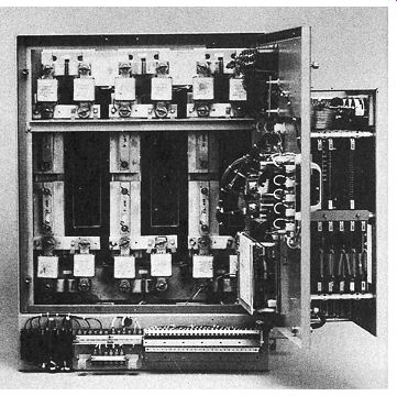
Solid-state drives are designed for easy installation. Threaded hublike power entries are provided for top and bottom conduit entry. En closure knockouts are also available and wire entry is made directly to incoming marked power terminals. Sufficient space is allowed around power terminals to ensure working room and easy installation of plug-in kits. Refer to ill. 4. Keeping these drives operating reliably shouldn't be too difficult. Modular construction makes troubleshooting easier. Components can be removed for repair or replacement. Leads disconnect simply by means of plug connectors. Replacement components are accessible. The visual control panel tells where the problems are.
ill. 3 Single-phase AC to DC motor control.
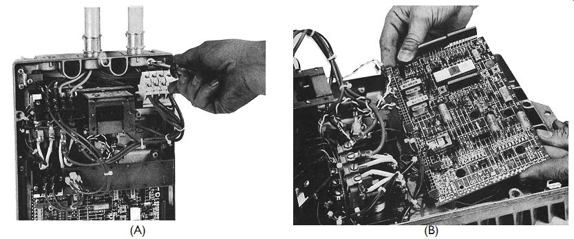
ill. 4 (A) Power leads fall straight to incoming termination with ample room
for wiring. Note the threaded conduit power entries at the top, which permit
quick installation. (B) Modular design allows for easy troubleshooting.
DC ADJUSTABLE SPEED CONTROL,THREE PHASE
Power Supply
Power conversion cells convert incoming three-phase AC power to the highly controllable DC power used in the armature of the drive motor. ill. 5 shows a diagram of a three phase, full-wave controlled rectifier connected to a load. The controlled rectifier uses SCRs- not uncontrolled diodes as shown in single phase rectifiers. Note that some single-phase units use SCRs also. Three-phase rectifiers provide smooth DC compared with half-wave single phase. This can be seen in ill. 6, looking at the top of the DC ripple (A, B, C).This ripple is further refined by filtering it through electronic circuits containing inductors and capacitors. The power supply takes the incoming three-phase power and transforms it to the proper voltage levels for the support circuitry to power the signal electronics, firing circuits, and excitation modules.
ill. 4 (A) Power leads fall straight to incoming termination with ample room
for wiring. Note the threaded conduit power entries at the top, which permit
quick installation. (B) Modular design allows for easy troubleshooting.
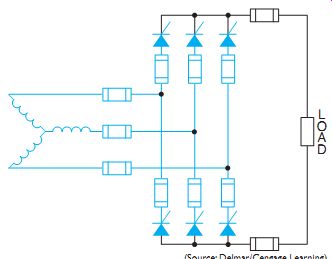
ill. 5 Three-phase, full-wave controlled rectifier with connected load.
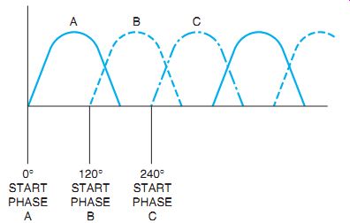
ill. 6 Rectified three-phase power.
Power Control
ill. 7 shows a three-phase power circuit for an adjustable speed drive system.
These systems are available in sizes ranging from about 5 to 2500 horsepower. The circuit diagram shows the circuit configuration of the power conversion system and the motor field excitation module. Three-phase power is routed through the fuse-protected legs of this converter and is delivered to the armature. Fuses on each leg provide better protection than line fuses against "shoot-throughs" and reversing inversion faults. SCRs are mounted with proper heat sinks (heat dissipators). Some of this may be seen in ill. 8. A main DC contactor isolates the armature when stopped.
The motor field may remain energized. If so, its heat helps prevent harmful moisture from forming in the motor due to condensation in a humid or damp environment. Instead of using a tachometer generator feedback for constant speed control, armature and field current feed back is obtained from shunts, more often used in connecting DC ammeters. These shunts are similar to a resistor. A millivolt drop is read across them, and this information is fed into the speed control circuit. The SCRs then act to control the motor at a constant speed under changing load conditions.
Signal Electronics
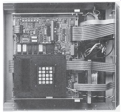
A signal electronics module provides the over all drive control. It contains a microprocessor and supporting control electronics mounted on printed wiring boards, ill. 9. The same signal electronics module can usually be used regardless of the size of the power electronics (with equipment from the same manufacturer).
In this way, the cost of the replacement modules inventory is reduced. It is also convenient for the maintenance personnel, because modules can be switched or interchanged when diagnosing a problem.
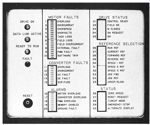
The microprocessor is the center of the control system. In addition to providing the SCR firing circuit, control, regulating functions, and drive sequencing, it can communicate with people. It also responds to feedbacks and reference commands, then adjusts both motor field and armature power accordingly. The micro processor also provides diagnostic information. To communicate this information, a number of techniques are available. E.g., an LED display panel provides indication of motor faults, converter faults, alarms, drive status, and drive configuration. If more than one fault occurs, each of the faults will activate a light and the first fault will ?ash. An amber- colored LED is energized on all key circuit boards after the microprocessor control checks each critical circuit. The amber, or white, LED light remains energized as long as the circuit's functional. Thyristor cell status lights are energized each time the indicated SCR is fired, thus indicating the operation of the SCR. If a printer is connected, English language and engineering term messages are received from the processor.
This information can be used to interrogate the drive unit. However, a keyboard and video monitor are required to do this. These are seen in ill. 10.
ill. 8 SCRs are mounted with proper heat sinks.
ill. 10 This wired control module for a drive sys tem is common in the better
drives, both AC and DC.
The keypad provides a high degree of diagnostics with a 16-character LED feedback in easily understood terms, as well as direct access to the drive.
ill. 9 Signal module contains a microprocessor and control electronics mounted
on printed wiring boards.
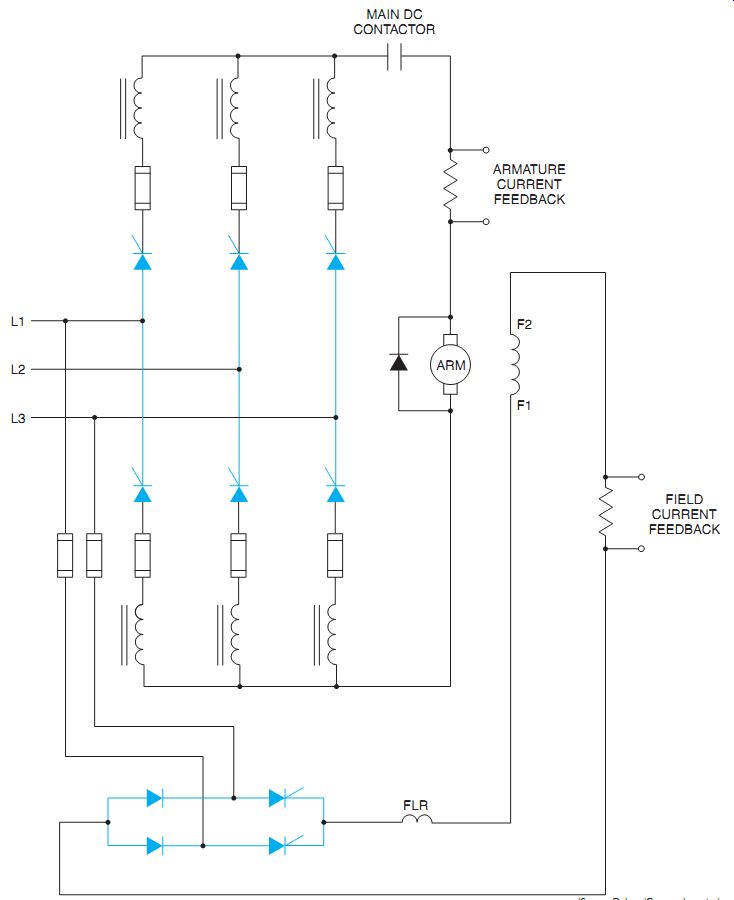
ill. 7 Three-phase AC feeding a DC adjustable speed drive power circuit.
SELF-TEST DIAGNOSTICS
When power is applied to the drive or when it's requested by an interactive command, each of the circuit boards is sequentially checked by the microprocessor. As each passes the self-test routine, the light for that board is energized and the sys tem progresses to the next board. After the signal electronics have been verified, the microprocessor fires each of the armature circuit SCRs one at a time. An SCR cell voltage sensor is used to indicate if the gating, fuse, and SCR are operational.
If both the signal (control) and the power electronics pass the test, the control is released for drive operation. If the test discovers a problem (failed board, SCR cells, fuses, open wire, and so on), the specific fault is displayed on the lighted panel or is printed out, and the drive isn't re leased for starting until the problem is corrected.
QUIZ
1. Where does the DC motor get its DC power?
2. How does a solid-state device start the motor?
3. Describe methods of feedback control for constant speed.
4. What method is used to sense armature and field current?
5. Describe methods of communication with a machine controller.
6. What might be a first step in troubleshooting a drive control?