AMAZON multi-meters discounts AMAZON oscilloscope discounts
Goals:
- • Describe the operation and applications of a synchronous motor.
- • Describe lagging and leading power factor and the causes of each.
- • Describe how the use of a synchronous motor improves the efficiency of an electrical system having a lagging power factor.
- • Identify a brushless synchronous motor.
One of the distinguishing features of the synchronous motor is that it runs without slip at a speed determined by the frequency of the connected power source and the number of poles it contains. This type of motor sets up a rotating field through stator coils energized by alternating current. (This action is similar to the principle of an induction motor.) An independent field is established by a rotor energized by direct cur rent through slip rings mounted on the shaft.
The rotor has the same number of coils as the stator. At running speed, these fields (north and south) lock into one another magnetically so that the speed of the rotor is in step with the rotating magnetic field of the stator. In other words, the rotor turns at the synchronous speed. Variations in the connected load don't cause a corresponding change in speed, as they would with the induction motor.
The rotor, ill. 1, is excited by a source of direct current so that it produces alternate north and south poles. These poles are then attracted by the rotating magnetic field in the stator. The rotor must have the same number of poles as the stator winding. Every rotor pole, north and south, has an alternate stator pole, south and north, with which it can synchronize.
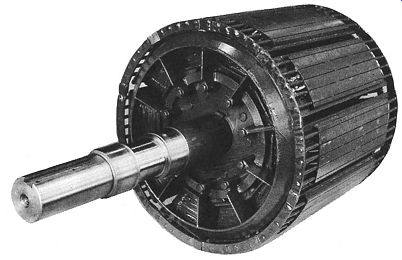
ill. 1 Rotor of 300-hp, 720-rpm synchronous motor.
The rotor has DC field windings to which direct current is supplied through collector rings (slip rings). The current is provided from either an external source or a small DC generator connected to the end of the rotor shaft.
The magnetic fields of the rotor poles are locked into step with-and pulled around by- the revolving field of the stator. Assuming that the rotor and stator have the same number of poles, the rotor moves at the stator frequency (in hertz) actually produced by the generator supplying the motor.
Synchronous motors are constructed almost exactly like alternators. They differ only in those features of design that may make the motor better adapted to its particular purpose.
A synchronous motor cannot start without help because the DC rotor poles at rest are alternately attracted and repelled by the revolving stator field. Therefore, an induction squirrel cage, or starting winding is embedded in the pole faces of the rotor. This is called an armortisseur (ah-more-ti-sir) winding.
This starting winding resembles a squirrel cage winding. The induction effect of the starting winding provides the starting, accelerating, and pull-up torques required. The winding is designed to be used only for starting and for damping oscillations during running. It cannot be used like the winding of the conventional squirrel cage motor. It has a relatively small cross- sectional area and will overheat if the motor is used as a squirrel cage induction motor.
The slip is equal to 100 percent at the moment of starting. Thus, when the AC rotating magnetic field of the stator cuts the rotor windings, which are stationary at startup, the induced voltages produced may be high enough to damage the insulation if precautions are not taken.
If the DC rotor field is either connected as a closed circuit or connected to a discharge resistor during the starting period, the resulting current produces a voltage drop that's opposed to the generated voltage. Thus, the induced voltage at the field terminals is reduced. The squirrel cage winding is used to start the synchronous motor in the same way it's used in the squirrel cage induction motor. When the rotor reaches the maximum speed to which it can be accelerated as a squirrel cage motor (about 95 percent or more of the synchronous speed), direct current is applied to the rotor field coils to establish north and south rotor poles. These poles then are attracted by the poles on the stator. The rotor then accelerates until it locks into synchro nous motion with the stator field.
Synchronous motors are used for applications involving large, slow-speed machines with steady loads and constant speeds. Such applications include compressors, fans and pumps, many types of crushers and grinders, and pulp, paper, rubber, chemical, flour, and metal-rolling mills, ill. 2.
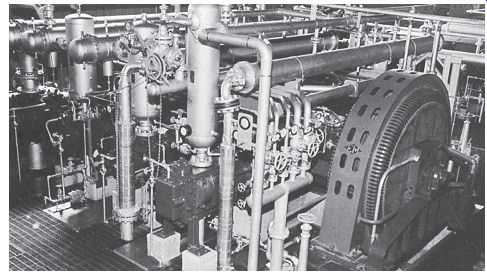
ill. 2 A 2000-hp, 300-rpm synchronous motor driving compressor.
POWER FACTOR CORRECTION BY SYNCHRONOUS MOTOR
A synchronous motor converts AC electrical energy into mechanical power. In addition, it also provides power factor correction. It can operate at a leading power factor or at unity. In very rare occasions, it can operate at a lagging power factor.
The power factor is of great concern to industrial users of electricity with respect to energy conservation. Power factor is the ratio of the actual power, being used in a circuit, expressed in watts or kilowatts, to the power apparently being drawn from the line, expressed in volt amperes or kilovolt-amperes (kVA). The kVA value is obtained by multiplying a voltmeter reading and an ammeter reading of the same circuit or equipment. Inductance within the circuit will cause the current to lag the voltage.
When the values of the apparent and actual power are equal or in phase, the ratio of these values is 1:1. In other words, when the voltage and amperage are in phase, the ratio of these values is 1:1. This is the case of pure resistive loads. The unity power factor value is the highest power factor that can be obtained. The higher the power factor, the greater is the efficiency of the electrical equipment.
AC loads generally have a lagging power factor. As a result, these loads burden the power system with a large reactive load. Refer to the induction motor in ill. 3. A synchronous motor should be operated at unity, or at its greatest leading power factor for the most efficient operation. This helps supply reactive power where required in the electrical system.
Synchronous motors are operated to offset the low-power factor of the other loads on the same electrical system. Therefore, the synchronous motor works to improve the power factor of the electrical system, while turning large, slow speed machines.
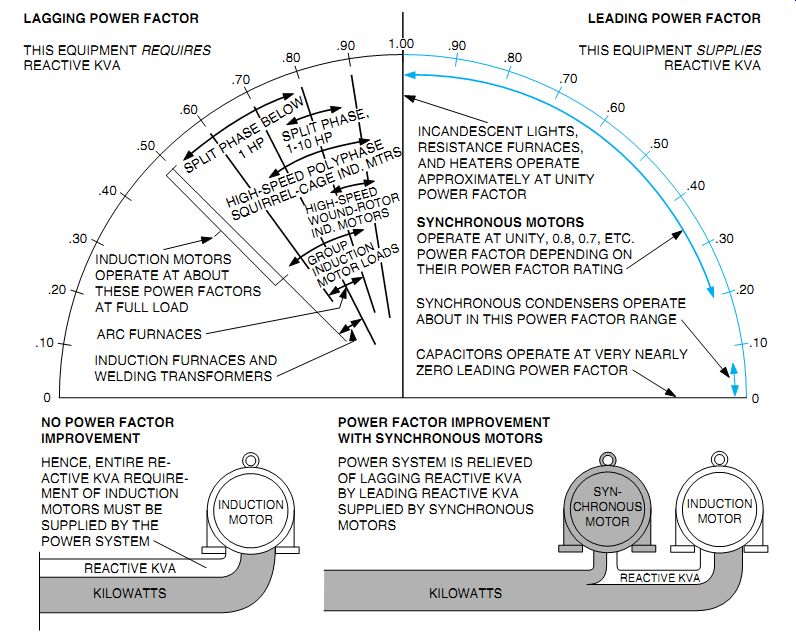
ill. 3 Power factor operation of various devices may be improved through the
use of synchronous motors.
LAGGING POWER FACTOR THIS EQUIPMENT REQUIRES REACTIVE KVA
LEADING POWER FACTOR THIS EQUIPMENT SUPPLIES REACTIVE KVA
BRUSHLESS SYNCHRONOUS MOTORS
NO POWER FACTOR IMPROVEMENT HENCE, ENTIRE RE ACTIVE KVA Requirement OF INDUCTION MOTORS MUST BE SUPPLIED BY THE POWER SYSTEM REACTIVE KVA KILOWATTS
POWER FACTOR IMPROVEMENT WITH SYNCHRONOUS MOTORS POWER SYSTEM IS RELIEVED OF LAGGING REACTIVE KVA BY LEADING REACTIVE KVA SUPPLIED BY SYNCHRONOUS MOTORS
CAPACITORS OPERATE AT VERY NEARLY ZERO LEADING POWER FACTOR SYNCHRONOUS CONDENSERS OPERATE ABOUT IN THIS POWER FACTOR RANGE SYNCHRONOUS MOTORS OPERATE AT UNITY, 0.8, 0.7, ETC.
POWER FACTOR DEPENDING ON THEIR POWER FACTOR RATING INCANDESCENT LIGHTS, RESISTANCE FURNACES, AND HEATERS OPERATE APPROXIMATELY AT UNITY POWER FACTOR
INDUCTION MOTORS OPERATE AT ABOUT THESE POWER FACTORS AT FULL LOAD INDUCTION FURNACES AND WELDING TRANSFORMERS ARC FURNACES
ill. 4 A brushless exciter contains a separate three-phase winding on the
rotor shaft.
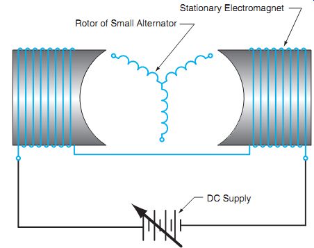
ill. 5 The brushless exciter uses stationary electromagnets.
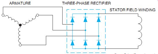
ill. 6 Basic brushless exciter circuit.
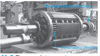
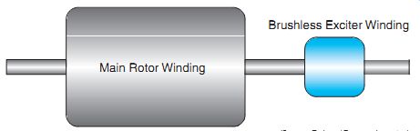
ill. 7 The rotor of a large synchronous motor with a brushless exciter. (E.g.,
from GE Industrial Systems, Fort Wayne, Indiana)
Another method for applying excitation cur rent to the rotor is with a brushless exciter. Rotors of this type contain a separate three-phase alternator winding mounted on the rotor shaft, ill. 4. Electromagnets are mounted on each side of the three-phase winding. The external direct-current supply provides power for the electromagnets, ill. 5. The amount of induced voltage in the three-phase winding is controlled by the strength of the magnetic field of the electromagnets. The output of the three-phase alternator winding is also connected to a three phase bridge rectifier mounted on the rotor shaft, ill. 6. The bridge rectifier converts the three-phase AC voltage into DC voltage. The DC voltage supplies the excitation current for the controlled by the external DC source, but there are no brushes or slip rings that can cause mechanical problems. The elimination of slip rings and brushes gives the synchronous motor equipped with a brushless exciter several out standing advantages:
++ Brush sparking is eliminated, reducing safety hazards in some areas.
++ Field control and excitation are provided by a static system, requiring much less maintenance.
++ Field excitation is automatically removed whenever the motor is out of step. Automatic resynchronization can be achieved whenever it's practical. rotor. The amount of rotor excitation is still
The rotor of a large synchronous motor with a brushless exciter winding is shown in ill. 7. More is written on this subject in Unit 42.
QUIZ:
1. Why is it necessary that the rotor and stator have an equal number of poles?
2. What is the effect of the starting winding of the synchronous motor on the running speed?
3. What are typical applications of synchronous motors?
4. Explain how the rotor magnetic field is established.
5. A loaded synchronous motor cannot operate continuously without DC excitation on the rotor. Why?
6. Why must a discharge resistor be connected in the field circuit for starting?
7. Depending on their power factor ratings, what is the range of the leading power factor at which synchronous motors operate?
8. At what power factor do incandescent lights operate?
9. At what power factor do high-speed, wound rotor motors operate? Select the best answer for the following items.
10. The speed of a synchronous motor is fixed by the
a. rotor winding
b. amortisseur winding
c. supply voltage
d. frequency of power supply and number of poles
11. Varying the DC voltage to the rotor field changes the
a. motor speed
b. power factor
c. phase excitation
d. slip
12. Amortisseur windings are located
a. in the stator pole faces
b. in the rotor pole faces
c. in the controller
d. leading the power factor
13. DC excitation is applied to the
a. starting winding
b. stator winding
c. rotor winding
d. amortisseur winding
14. Induction motors and welding transformers require magnetizing current, which causes
a. lagging power factor
b. leading power factor
c. unity power factor
d. zero power factor
15. A synchronous motor can be used to increase the power factor of an electrical system by
a. reducing the speed
b. overexciting the stator field
c. operating at unity power factor
d. applying DC to the stator field