AMAZON multi-meters discounts AMAZON oscilloscope discounts
Goals:
• Identify terminal markings for a push-button synchronizing controller and synchronous motor.
• Describe two functions of synchronous motor control
• Connect synchronous motors and synchronizing controls.
• Recommend troubleshooting solutions for synchronous motors and controls.
• Describe adjustments that can be made to the circuit of a synchronous motor and control to obtain a power factor of unity or greater.
• Synchronize a synchronous motor.
There are two basic functions of synchronous motor control in starting:
1. To start the motor as an induction motor.
The motor can be started using any of the typical induction motor starting schemes.
These include connecting the motor across the line or the use of autotransformers, primary resistors, or other devices, depending on the size of the motor.
2. To bring the motor up to synchronous speed by exciting the DC field. The principal difference between synchronous motor control and induction motor control is in the control of the field. Two voltages are needed, AC for the stator and DC for the rotor.
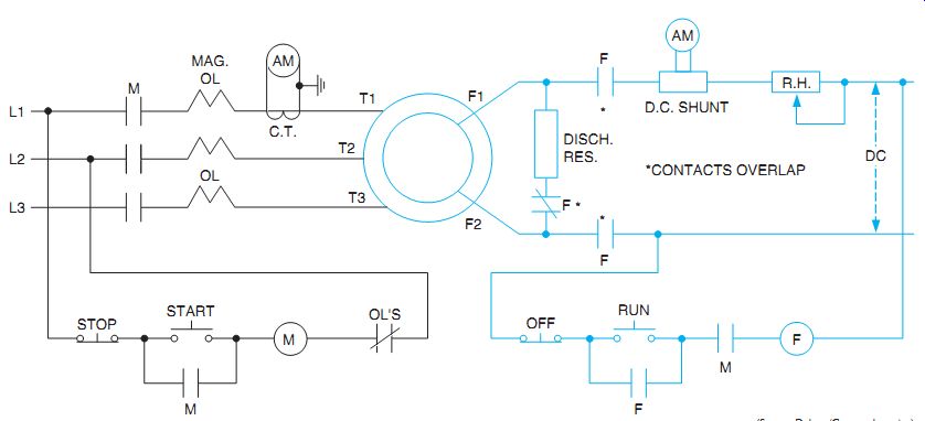
In ill. 1, the synchronous motor is started as an induction motor by pressing the start button. When the motor reaches its maximum speed, the run push button is closed to energize coil (F) and close the DC excitation contacts (F). These contacts, in turn, open the field discharge normally closed contact (F) and energize the DC field, F1 and F2 of the motor. The normally closed contact F opens after normally open F contacts close to avoid a high induced voltage in the field. The stator acts like a transformer primary. The DC field circuit receives an induced current (as does a transformer secondary).When the stator is energized, the rotor circuit must be closed at all times. The overlap ping normally closed contacts F keep the loading resistor in the circuit. Without it, dangerous high voltages are induced, which may rupture the insulation on the rotor windings. The induced current in the rotor resistor circuit keeps the induced voltage at a tolerable level.
The discharge resistor also prevents arcing at the contacts. In addition, it dissipates the self-induced voltage from the collapsing DC magnetic field of the rotor windings.
Note in ill. 1 that the normally open contacts M in the F coil circuit prevent the DC field from being energized before the motor is started. These interlocking contacts close only after the AC control is energized. Pushing the stop button on the AC side also opens the DC supply. If the motor does not reach synchronous speed with the first try, the off button should be pressed. The run push button can then be reengaged.
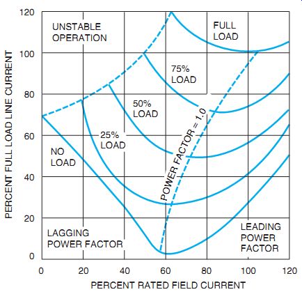
The ammeter and rheostat shown in the DC circuit in ill. 1 control the excitation current. The unity power factor of the motor can be found by adjusting the rheostat to obtain a minimum reading on the AC ammeter in the stator circuit, ill. 2.

ill. 1 Elementary diagram of push-button synchronizing.

ill. 2 Line current versus field current for a motor with a unity power factor.
Adjustments of the circuit may cause field currents, or line currents, in excess of the motor rating. As a result, electrical instruments must be provided to monitor various circuit values.
The operator can then prevent equipment stop page due to overload tripping. The readings of the instruments must not exceed the rated values shown on the motor nameplate.
The excitation current can be applied manually to excite the DC field to bring the motor up to synchronous speed. For this operation, however, it's the operator who must make the difficult judgment of when the north and south poles of the rotor and stator fields are paired and the motor is ready for synchronous operation. For this reason, the system does not provide automatic motor synchronization. However, it's a comparatively simple and in expensive method.
QUIZ:
1. What are the two basic functions of synchronous motor control?
2. What is the purpose of the interlock (M) in the DC control circuit?
3. If all of the control circuits are AC--and DC isn't available--what will be the result of energizing all of the contactor coils?
4. When the rotor and stator fields lock into step, why may the reading of the AC ammeter decrease?
5. Why is manual field application not completely satisfactory?
6. If a synchronizing attempt fails, what procedure should be followed?
7. In ill. 2, approximately what is the percentage of current drawn from the line when the field current is adjusted to 100 percent of its capacity at full motor load?
8. Why are the AC ammeter and DC meter necessary in the circuit of ill. 1?
9. Why is the operation of the field contacts (F) overlapped in ill. 1?