AMAZON multi-meters discounts AMAZON oscilloscope discounts
Goals:
• Describe slip power recovery and the method used to achieve it.
• Compare the solid-state method of control with resistor methods.
• Describe how speed control is accomplished electronically.
• Connect power factor correction capacitors into a motor circuit.
SOLID-STATE ADJUSTABLE SPEED CONTROLLER
An ideal solid-state adjustable speed controller is a modern, energy-saving method of controlling motor speed. It provides stepless, smooth adjustable speed control of AC wound rotor induction motors. It also recovers slip loss power when the motor runs at less than rated speed. This means that the controller will operate a wound rotor induction motor on less electrical power from the AC power line as com pared with resistors, liquid rheostats or any reactor controls, and fluid or magnetic clutches.
The solid-state secondary speed controller is ideally suited for any application where a motor must run at less than its rated maximum speed, such as in water and waste water pumping and various fan applications. Speed control is accomplished by controlling motor rotor cur rent, thereby controlling the motor torque.
Escalating energy costs have made efficiency an important consideration in determining which adjustable speed controller is best suited for a specific application.
SLIP POWER RECOVERY
A slip power recovery controller consists of a three-phase, full-wave diode rectifier, which converts the motor secondary voltage to a DC volt age, a filter reactor to smooth the rectification ripple, and a line commutated thyristor/inverter (DC to AC) synchronized to the power line to return motor slip loss power, ill. 1.
This adjustable controller permits stepless speed control of the motor. On reaching full speed, motor secondary shorting thyristors are automatically energized and the thyristor inverter is turned off. This eliminates reactive current returned to the power system during full-speed operation.
Electronic circuitry is arranged on plug-in circuit cards, or modules, and are located on a plug-in rack. Electronic cards, or modules, are coated to protect against damage due to moisture and a corrosive environment. Card-edge connectors are generally gold coated to ensure reliable contact between the card and the rack terminals. Cards and modules are also keyed to prevent in-correct insertion. LEDs are provided to indicate the operating status to assist in troubleshooting.
An instantaneous overcurrent circuit detects a fault condition, activates circuitry electronically to clear the fault condition, and allows the controller to resume normal operation. All controller startup adjustments are located on a drive adjust card. Electronic circuits are located on the remaining cards. Ideally, these are replaceable without readjustment of the controller.
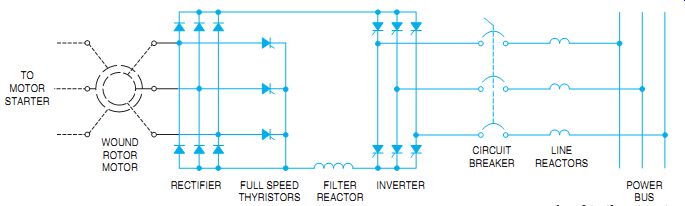
ill. 1 Elementary diagram of a slip power recovery system. Motor starters
have been shown.
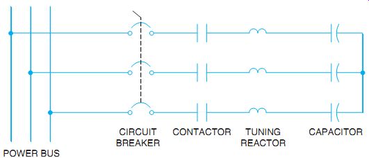
ill. 2 Elementary diagram of power factor correction capacitors.
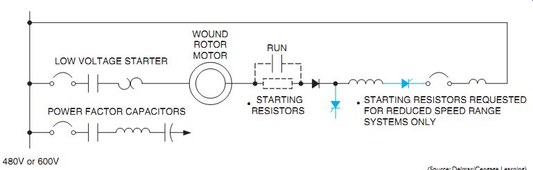
ill. 3 Line diagram of solid-state control with power factor correction. STARTING
RESISTORS REQUESTED FOR REDUCED SPEED RANGE SYSTEMS ONLY
POWER FACTOR CORRECTION CAPACITORS
Power factor correction is recommended for all slip power recovery systems. During the operation of a slip power recovery control system, motor secondary current is flowing back into the power line. As the motor speed increases, the current becomes more reactive and if not corrected would result in a very poor power factor. The correct method of connecting the power factor correction capacitors in the circuit's shown in ill. 2.
ill. 3 is a line diagram showing a total operating system. Starting resistors are required for reduced speed range systems only.
QUIZ:
1. If someone told you that the solid-state power recovery controller is a perpetual motion machine, what would your reaction be?
2. How do solid-state adjustable speed controllers compare with secondary resistor control?
3. Basically, how is speed control accomplished?
4. Why are capacitors connected into the power circuit?