AMAZON multi-meters discounts AMAZON oscilloscope discounts
Goals:
- • Identify terminal markings for wound rotor motors used with automatic speed controllers.
- • Describe the purpose and function of automatic speed controllers for wound rotor motors.
- • Connect wound rotor motors and controllers for automatic speed control.
- • Recommend solutions for troubleshooting problems with these motors.
Automatic speed control of a wound rotor motor can be obtained with the use of pilot devices.
It is possible to control acceleration and deceleration and maintain selected speeds. The line diagram of a typical controller using pilot de vices to provide automatic speed control is shown in ill. 1.
Assume that the wound rotor motor in ill. 1 is coupled to a fluid pump in a liquid controlled system. The operation of such a system is described as follows: To maintain the liquid level automatically, the selector switch is placed in the automatic position. As the liquid rises, the master float switch (MFS) closes the circuit to the control switch. As the fluid continues to rise, float switch FS1 energizes control relay CR1. CR1 closes the main starter contacts M to start the motor in slow speed and energize timing relay T1. If the motor speed is too slow to permit proper fluid delivery, the changing liquid level in the tank eventually closes the third float switch (FS2). CR2 is then energized through the now closed contacts of T1 to operate the first accelerating contactor (1A). In addition, the first bank of resistance is removed from the circuit, and the second time-delay relay (T2) is energized. This process continues until a motor speed is reached that maintains the liquid in the tank at a constant level. If the control selector switch is placed on manual, the float switches are bypassed and the motor must start with all of the resistance inserted in the secondary circuit. The motor must follow the preset timing sequence until all resistance is removed to obtain the maximum operation from the pump.
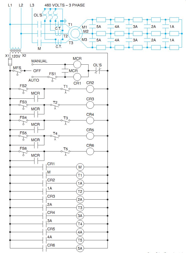
ill. 1 Line diagram of wound rotor motor controller using pilot devices to
provide automatic speed control. It includes control of acceleration and deceleration and maintenance of selected speeds.
QUIZ:
1. Referring to ill. 1, can the motor be started in the manual position when there is no fluid in the tank? Why?
2. Assuming that this system is installed in an industrial mixing or processing tank and that the tank input decreases, what actions will be initiated by the control system?
3. How does the connection of the overload relay contacts cause all other control relays and contactors to drop out?