AMAZON multi-meters discounts AMAZON oscilloscope discounts
Goals:
- • Identify terminal markings for four-speed, two-winding (consequent pole) motors and controllers.
- • Describe the purpose and function of four-speed, two-winding motor starters and motors.
- • Describe the purpose and function of a compelling relay, an accelerating relay, and a decelerating relay.
- • Connect and troubleshoot four-speed, two-winding controllers and motors.
Four-speed, consequent pole, squirrel cage motors have two reconnectable windings and two speeds for each winding.
OPERATIONAL SEQUENCE
Standard starters generally are connected so that the operator can start the motor from rest at any speed, or change from a lower speed to a higher speed. Before change is made from a higher to a lower speed, the stop button must be pressed. This arrangement protects the motor and the driven machinery from the excessive line current and shock that results when a motor running at a high speed is reconnected to run at a lower speed.
Multispeed starters are provided with mechanical and electrical interlocking to avoid the possibility of short-circuiting the line or connecting more than one speed winding at the same time.
COMPELLING RELAYS
Standard starters are not equipped with compelling relays. Such relays ensure that the motor starts at the lowest speed or that acceleration is accomplished in a series of steps. (These devices are described in previous units covering multispeed control.) However, when the type of motor used or the characteristics of the load involved make it necessary to use a particular starting sequence, there are three types of relays available to accomplish the function required: compelling relays, accelerating relays, and decelerating relays.
Form 1 -- Compelling Relay
When this type of relay is used, the motor must be started at low speed before a higher speed can be selected. The motor can be started only by pressing the low-speed push button. If any other push button is pressed, nothing will happen. This arrangement ensures that the motor first moves the load only at low speed.
The stop button must be pressed before a change can be made from a higher speed to a lower speed.
Form 2 -- Accelerating Relays
When the starter is equipped with a Form 2 accelerating relay, the final speed is determined by the button pressed. The motor is started at low speed and is then accelerated automatically through successive speed steps until the selected speed is reached. Definite time intervals must elapse between each speed change. Individual timing relays are provided for each interval.
Each relay is adjustable. The stop button must be pressed before a change can be made from a higher speed to a lower speed.
Decelerating Relays
This type of relay is similar in action to a Form 2 accelerating relay. The difference is that it controls a stepped deceleration from a high speed to a lower speed. Definite time intervals must elapse between each speed change.
Tremendous strains are placed on both the motor and the driven machinery when a change from a higher speed to a lower speed is made and the motor isn't allowed to slow down to the de sired speed. Such strain is avoided if a definite, adjustable time interval is provided between speeds when the motor is decelerating.
Using three-wire, push-button control and decelerating relays, it's possible to select any speed less than that at which the motor is running by pressing the proper push button. Once this push button is pressed, it de-energizes the contactor driving the motor at the higher speed and energizes the timing relays. After a preset time period, the timing relays energize the contactor to drive the motor at the lower speed. As succeedingly lower speeds are selected, there is an increase in the elapsed time between disconnecting the higher speed winding and connecting the lower speed winding.
When the two-wire control devices, such as pressure or float switches, are used to control motors at various speeds, decelerating relays should always be used. The only exception to this statement is in the event that both the motor manufacturer and the machine manufacturer approve the intended application and agree that decelerating relays are not necessary.
ill. 1 is an elementary diagram of a four-speed controller that can be used on a two winding motor. This circuit's for a standard starter arrangement that isn't equipped with compelling relays. (Remember that such relays permit starting only at the lowest speed.) This controller has electrical interlocks that prevent an operator from changing to different speeds without pressing the stop button. A definite time interval must elapse between each speed change on deceleration. The motor should be al lowed to slow to the speed desired before a transfer to a lower speed is made.
In the motor connection table in ill. 1, note that the windings are connected alternately during acceleration. If the first winding is 6 and 12 poles and the second winding is 4 and 8 poles, then the successive pole connections for acceleration from low speed to high speed are 12, 8, 6, and 4. ill. 2 shows common motor connections for four-speed, three-phase, two-winding motors; all have different speeds. Note that the idle winding remains open circuited on given speeds. In this way an unnecessary electrical load isn't imposed on the energized winding. This load would result from transformer action that creates circulating currents in the secondary, idle winding.
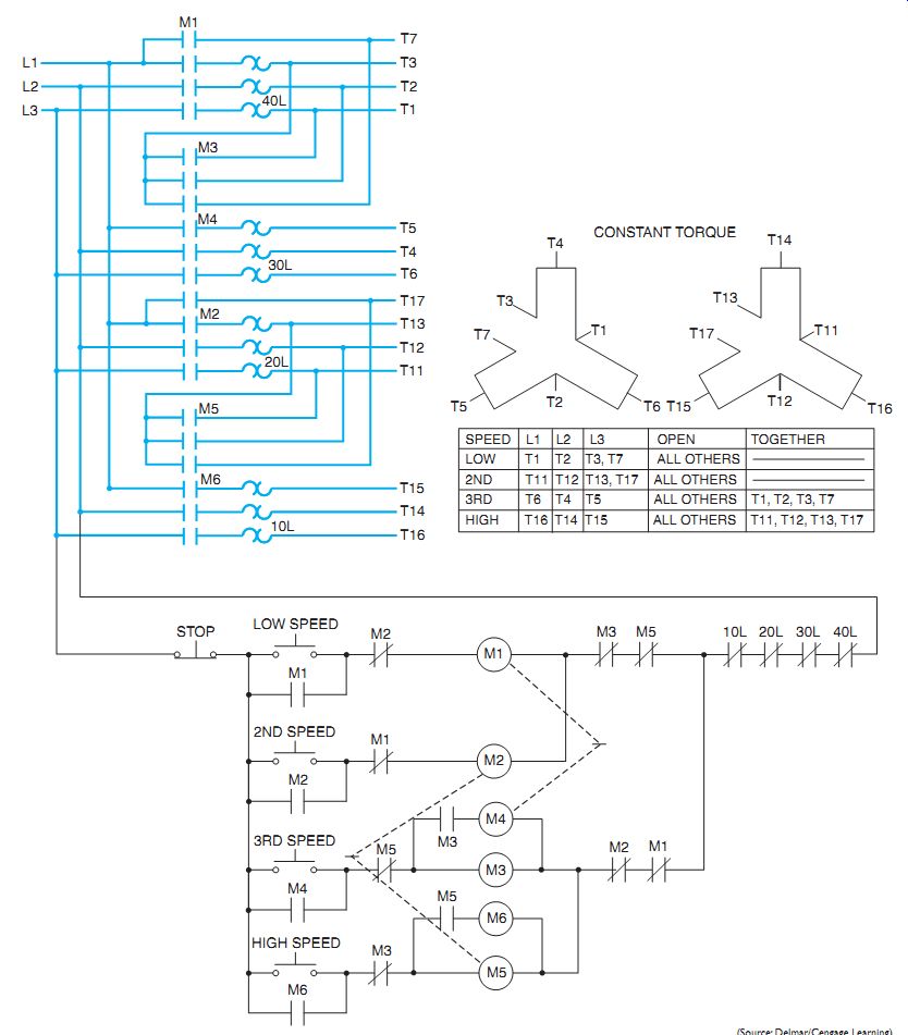
ill. 1 Elementary diagram of a four-speed, two-winding controller.
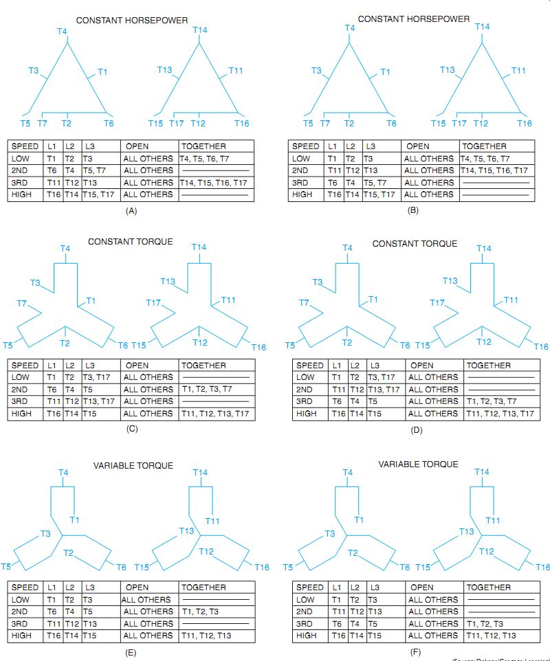
ill. 2 Typical arrangements for four-speed, three-phase, two-winding motors.
QUIZ:
1. When a four-speed, two-winding motor is running, why is it desirable to allow the idle winding to remain open circuited?
2. In ill. 1,what is the function of this particular arrangement of electrical interlocks?
3. Why are definite time intervals required between each speed change on deceleration?
4. What is the primary reason for using a compelling relay?
5. What is the purpose of an accelerating relay?
6. When is it most important to use decelerating relays for multispeed installations?
7. Why are different motor connections shown for what appears to be the same motor in the various diagrams in ill. 2?
8. How many windings are required for three-speed motors?