AMAZON multi-meters discounts AMAZON oscilloscope discounts
Goals:
- • Identify terminal markings for two-speed, one-winding motors and controllers.
- • Describe the purpose and function of two-speed, one-winding motor starters and motors.
- • Connect two-speed, one-winding controllers and motors.
- • Connect a two-speed starter with reversing controls.
- • Recommend solutions for troubleshooting these motors and controllers.
Certain applications require the use of a squirrel cage motor having a winding arranged so that the number of poles can be changed by reversing some of the currents. If the number of poles is doubled, the speed of the motor is cut approximately in half.
The number of poles can be cut in half by changing the polarity of alternate pairs of poles, ill. 1. The polarity of half the poles can be changed by reversing the current in half the coils, ill. 2.
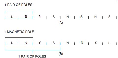
ill. 1 (A) Eight poles for low speed; (B) four poles for high speed.
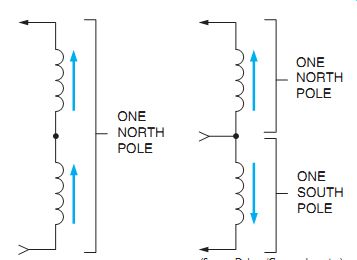
ill. 2 The number of poles is doubled by reversing current through half a
phase. Two speeds are obtained by producing twice as many consequent poles
for low-speed operation as for high speed.
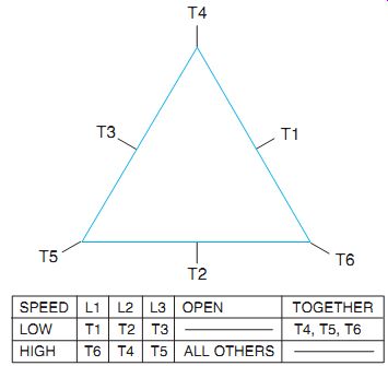
ill. 3 Connection table for three-phase, two-speed one-winding constant
horsepower motor.
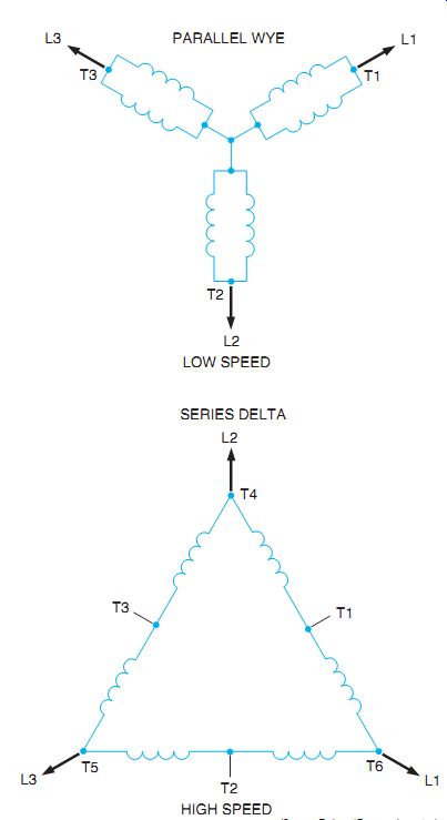
ill. 4 Three-phase, two-speed, one-winding constant horsepower motor connections
made by motor controller.
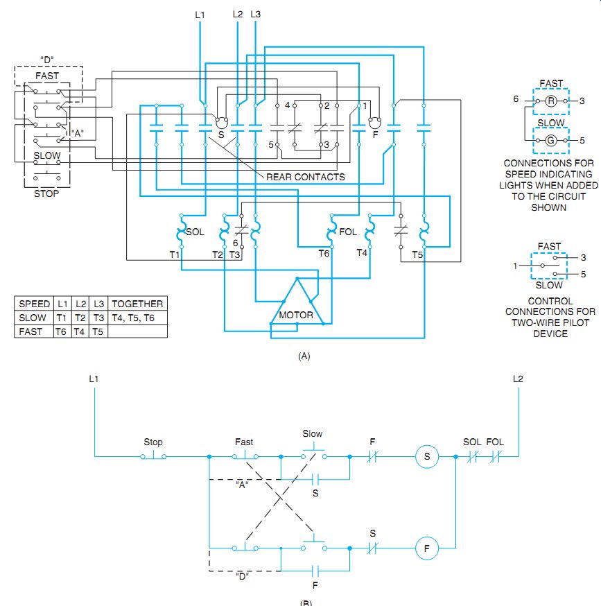
ill. 5 Wiring diagram (A) and line diagram (B) of an AC, full-voltage, two-speed
magnetic starter for single-winding (reconnectable pole) motors.
CONNECTIONS FOR SPEED INDICATING LIGHTS WHEN ADDED TO THE CIRCUIT SHOWN CONTROL CONNECTIONS FOR TWO-WIRE PILOT DEVICE
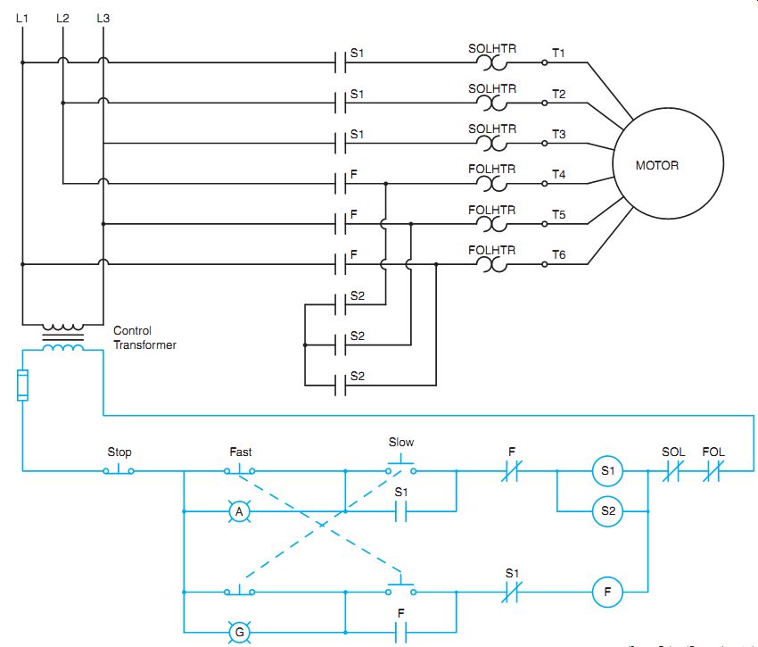
ill. 6 A circuit for controlling a two speed consequent pole motor using contactors
with three load contacts.
If a stator field is laid flat (as in ill. 1) the established stator field must move the rotor twice as far in Part (B) as in Part (A) and in the same amount of time. As a result, the rotor must travel faster. The fewer the number of poles established in the stator, the greater is the speed in r/min of the rotor.
A three-phase squirrel cage motor can be wound so that six leads are brought out, ill. 3. By making suitable connections with these leads, the windings can be connected in series delta or parallel wye, ill. 4. If the winding is such that the series delta connection gives the high speed, then the horse power rating is the same at both speeds. If the winding is such that the series delta connection gives the low speed and the parallel wye connection gives the high speed, then the torque rating is the same at both speeds.
Consequent pole motors have a single winding for two speeds. Extra taps can be brought from the winding to permit reconnection for a different number of stator poles. The speed range is limited to a 1:2 ratio, such as 600-1200 rpm or 900-1800 rpm.
Two-speed, consequent pole motors have one reconnectable winding. However, three-speed, consequent pole motors have two windings, one of which is reconnectable. Four-speed consequent pole motors have two reconnectable windings.
Referring back to the motor connection table in ill. 3, note that for low-speed operation, T1 is connected to L1; T2 to L2; T3 to L3; and T4, T5, and T6 are connected together. For high-speed operation, T6 is connected to L1; T4 to L2; T5 to L3; and all other motor leads are open.
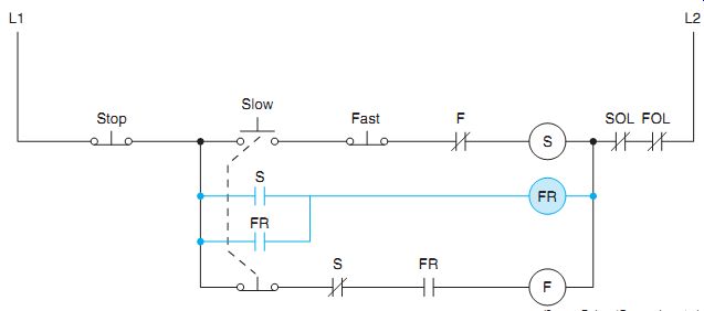
ill. 7 Two-speed control circuit using a compelling relay.
ill. 5(A) and (B) illustrates the circuit for a size 1, selective multispeed starter connected for operation with a reconnectable, constant horsepower motor. The control station is a three-element, fast-slow-stop station connected for starting at either the fast or slow speed. The speed can be changed from fast to slow or slow to fast without pressing the stop button between changes. If equipment considerations make it desirable to stop the motor be fore changing speeds, this feature can be added to the control circuit by making connections "D" and "A," shown in ill. 5 by the dashed lines. Adding these jumper wires eliminates push-button interlocking in favor of stopping the motor between speed changes. This feature may be desirable for some applications.
Connections for the addition of indicating lights or a two-wire pilot device instead of the control shown are also given.
The circuit illustrated in ill. 5(A) requires the use of a contactor with five load contacts. Circuits of this type are often constructed using contactors that contain three load contacts because they are more readily available.
A schematic diagram of a circuit of this type is shown in ill. 6. The circuit permits the motor speed to be changed without pressing the stop button. According to the chart in ill. 5(A), terminals T4, T5, and T6 must be connected together for low speed operation.
Two contactors will be employed when low speed is selected. The contactors will be identified as S1 and S2. The fast speed contactor will be identified as F. A separate overload relay for each speed is required because the full load cur rent for each speed will be different. Pilot lamps have been added to the circuit to indicate motor speed. An amber colored lamp will indicate slow speed and a green lamp will indicate fast speed.
A compelling-type control scheme is shown in ill. 7. These connections mean that the operator must start the motor at the slow speed. This controller cannot be switched to the fast speed until after the motor is running.
When the slow button is pressed, the slow speed starter S and the control relay FR are energized. Once the motor is running, pressing the fast button causes the slow-speed starter to drop out. The high-speed starter is picked up through the normally closed interlock contacts S of the slow-speed starter and through the normally open contacts of control relay FR. The normally open contacts of control relay FR will now close.
If the fast button is pressed in an attempt to start the motor, nothing will happen because the normally open contacts of control relay FR will prevent the high-speed starter from energizing.
When the fast button is pressed, it breaks a circuit but does not make a circuit. This scheme is another form of sequence starting.
MISTAKEN REVERSAL CAUTION
When multispeed controllers are installed, the electrician should check carefully to ensure that the phases between the high- and low speed windings are not accidentally reversed.
Such a phase reverse will also reverse the direction of motor rotation. The driven machine should remain disconnected from the motor until an operational inspection is complete. The upper oil inspection plugs (pressure plugs) in large gear reduction boxes should be removed.
Failure to remove these plugs may create bro ken casings if the motor is reversed accidentally.
Machines can be damaged if the direction of rotation is changed from that for which they are de signed. In general, the correct rotational direction is indicated by arrows on the driven machine.
ill. 9 Typical motor connection arrangement for three-phase, two-speed, one-winding motors. These connections conform to NEMA and ASA standards. (All possible arrangements are not shown.)
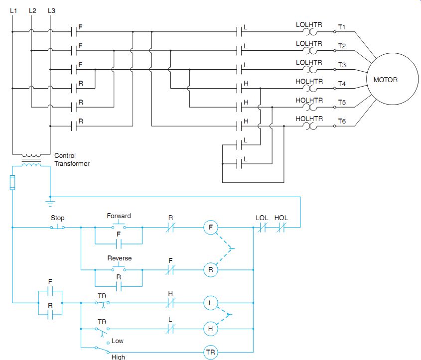
ill. 8 A forward-reverse two-speed control circuit. CONSTANT HORSEPOWER CONSTANT
TORQUE VARIABLE TORQUE
TWO-SPEED STARTER WITH REVERSING CONTROLS
ill. 8 is a diagram of a two-speed, reversing controller. The desired speed, high or low, is determined by the setting of a two position switch labeled Low and High. The load circuit consists of forward and reverse contactors as well as a contactor that contains three load contacts for high speed and a contactor that contains five load contacts for low speed. The circuit provides automatic acceleration to high speed in either the forward or reverse direction. The circuit operates as follows:
++ The direction of rotation is determined by pressing the forward or reverse push but ton. The forward-reverse circuit's interlocked electrically and mechanically in the same manner as a standard forward reverse control as discussed in Unit 21.
++ If the selector switch is set in the high position, the motor will start in low speed in the direction selected because a current path exists through the normally closed TR contact, and normally closed H contact to L contactor coil. The L and H contactors are electrically and mechanically interlocked in the same manner as the forward-reverse contactors.
++ Since the selector switch is set in the high position, a current path also exists to the coil of timer TR.
++ After some period of time, the normally closed TR contact opens and de-energizes contactor coil L. The normally open TR contact closes and provides a current path through the now closed L contact to contactor coil H causing the motor to accelerate to high speed.
++ The motor will remain in the selected speed until the stop push button is pressed.
++ If the selector switch is set in the low position, a current path is never established to TR timer and the motor will continue to operate in low speed until the stop push button is pressed.
++ An overload in either the low or high speed setting will de-energize the control circuit.
QUIZ:
1. The rotating magnetic field of a two-pole motor travels 360 electrical degrees. How many mechanical degrees does the rotor travel?
2. How can two speeds be obtained from a one-winding motor?
3. What will happen if terminals T5 and T6 in ill. 3 are interchanged on high speed?
4. Is the motor operating at high speed or low speed when it's connected in series delta? In parallel wye?
5. Describe the operation of the line diagram in ill. 5(B) by adding jumper "D" only.
6. Describe the operation of ill. 5(B) by adding jumper wire "A" to the original circuit.
7. In ill. 7, the motor cannot be started in high speed. Why?
8. Draw a schematic diagram of a two-speed control circuit using a standard-duty selector switch for the high and low speeds. Add a red pilot light for fast speed and a green pilot light for low speed. Omit "A" and "D" jumper wires.