AMAZON multi-meters discounts AMAZON oscilloscope discounts
Goals:
- • Identify terminal markings for two-speed, two-winding motors and starters.
- • Describe the purpose and function of two-speed, two-winding motor starters.
- • Describe how to obtain different speeds for AC squirrel cage motors.
- • Connect two-speed, two-winding controllers and motors.
- • Recommend solutions for troubleshooting these motors and controllers.
THE MOTOR
The squirrel cage induction motor is the most widely used industrial motor. It is simple and less expensive than most other motors. Essentially, it's a constant-speed motor. Some models, however, are made to operate at several fixed speeds. To do this, the motor manufacturer changes the number of poles for which the stator is wound. The operating principle on which the squirrel cage motor is based calls for a rotor revolving within a stator; this is due to the action of a rotating magnetic field. The speed of the revolving field is deter mined by the frequency of the alternating current (expressed in hertz) supplied by the alternator and by the number of poles on the stator. The formula defining speed in rpm is:
Speed in rpm = 60 x Hertz/ Pairs of Poles
The metric abbreviation r/min (revolutions per minute) refers to the synchronous speed of the motor. At the synchronous speed, the rotor speed equals the rotating magnetic field speed. Practically, however, this synchronous speed isn't achieved due to slip, or the lag, of the rotor behind the rotating stator field. The phrase pairs of poles is used to indicate that motor poles are always in pairs; a motor never has an odd number of poles.
Using the formula for speed, the synchronous speed of a two-pole motor supplied by 60-hertz electrical energy is determined as follows:
60x 60 / 1= 3600 rpm
The motor will run just below the synchro nous speed due to slip. The design of the motor will determine the percentage of slip. This value isn't the same for all motors.
CONTROLLERS
Line-voltage, ac multispeed starters, ill. 1, are designed to provide control for squirrel cage motors operating on two, three, or four different constant speeds, depending on their construction. The use of an automatic starter and a control station gives greater operating efficiency. In addition, both the motor and the machines are protected against improper sequencing or rapid speed change. Protection against motor overload at each speed is necessary.
Motors with separate windings have a different winding for each speed required. Although this type of motor is slightly more complicated in construction, and thus more expensive, the controller is relatively simple. Assuming the frequency is constant, two-winding motors will operate on each winding at the speed for which they are wound.
In the control arrangement in ill. 2, note that the motor can be started in either speed. However, the stop button must be pressed to transfer from high speed to the low speed. The starter shown in the figure is pro vided with a mechanical interlock between the L and H starters. Auxiliary contact interlocks are also provided.
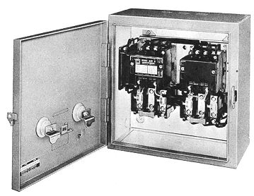
ill. 1 Magnetic controller for two-speed, two winding (separate winding) motor.
(E.g., from Schneider Electric)
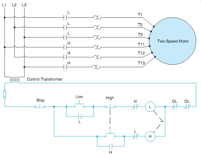
ill. 2 Schematic diagram of two-speed, two-winding three-phase motor.
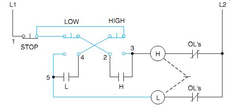
ill. 3 Elementary diagram of push-button interlock and transfer to either
speed without stopping.
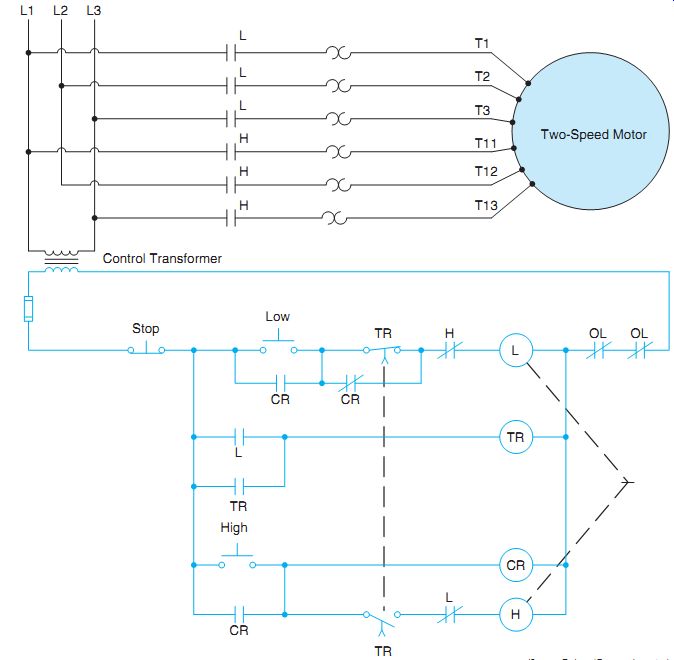
ill. 4 Automatic speed control for a two-speed, two-winding three-phase motor.
ill. 3 illustrates push-button inter locking through the use of combination push buttons. The figure also demonstrates that a transfer can be made to either speed without touching the stop button. However, rapid and continued speed transfers may activate the over load relays. To prevent this, the control scheme can be equipped with time-delay relays that will provide a time lag between the speed changes.
When the motor is operating, the inactive winding must be open-circuited. This is done to prevent circulating current due to transformer action between the idle winding and the energized winding.
ill. 4 illustrates an automatic speed control for a two-speed, two-winding three-phase motor. The circuit's so designed that a certain amount of time must pass before the motor can be changed from low to high speed. Assume that timer TR is set for a delay of 10 seconds. If the low-speed push button is pressed, a circuit's completed through the normally closed CR contact and the normally closed H contact to motor starter L. When the L starter energizes, the motor starts in low speed and the normally open L auxiliary contact closes to energize the coil of timer TR. At the same time, the normally closed L auxiliary contact connected in series with H starter coil opens. After a delay of 10 seconds, the two TR timed contacts change position. The normally closed TR contact connected in series with L starter coil opens, but the circuit's maintained through the normally closed CR contact. The normally open TR contact connected in series with H starter coil closes, but a circuit's not completed to the coil because of the normally open CR contact and the normally closed L auxiliary contact that's now open.
If high speed is desired, the high push button can be pressed, energizing control relay CR and causing all CR contacts to change position. The normally closed CR contact opens and interrupts the power to L starter coil. This permits the normally closed L auxiliary contact connected in series with H coil to reclose. The normally open CR contact connected in parallel with the high push button closes and provides a current path to both the CR coil the H starter coil through the now closed TR contact and closed L contact. The stop button must be pressed before the motor can be operated in low speed again.
If the motor isn't running and the high push button is pressed, CR control relay energizes, causing all CR contacts to change position. The normally open CR contact connected in parallel with the low-speed push button closes and pro vides a current path through the closed TR contact and closed H contact to starter coil L. The motor starts in low speed and the normally open L auxiliary contact connected in series with TR timer coil closes. When TR time energizes, the normally open TR instantaneous contact closes to maintain the circuit when the L contact reopens. After a 10-second time delay, both TR timed contacts change position. The normally closed TR contact connected in series with L starter coil opens and disconnects the starter from the power line. Note that because the normally closed CR contact in now open, a current path does not exist around the TR contact. When L starter de-energizes, the normally closed L auxiliary contact connected in series with H coil recloses, completing a current path through the closed CR contact, and closed TR timed contact. The motor will continue to operate in high speed until the stop button is pressed or an overload occurs. Connections for two-speed, separate winding, three-phase motors are shown in ill. 5.
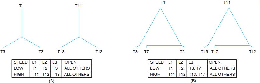
ill. 5 Connections for three-phase, two-speed, two-winding (separate winding)
motors (A) star and (B) delta.
QUIZ:
1. Excluding slip, at what speed (r/min) will an eight-pole, 60-hertz, 240-volt motor run?
2. What is meant by the description "separate winding, two-speed motor"?
3. What will happen if an operator makes too many rapid transitions from low to high speed and back on a two-speed motor?
4. Why are there four motor contacts for high and low speeds in ill. 4?
5. In ill. 4,what does the broken line between both time-delay contacts (TR) mean?
6. When the high button is depressed in ill. 4,what prevents the high-speed starter from closing immediately?
7. Which coils are energized immediately when the high push button is closed in ill. 4?
8. At what speed can a four-pole, 240-volt, 5-hp, 50-hertz motor operate?
9. What is meant by the "compelling action" produced by an accelerating relay?
10. Is it necessary to press the stop button when changing from a high speed to a low speed in ill. 4? Why or why not?