AMAZON multi-meters discounts AMAZON oscilloscope discounts
Goals:
• Describe and draw how a solid-state controller is connected to an existing electromagnetic starter.
• Describe additional features of a solid-state controller.
• Describe electrical noise and how to help prevent it.
• Discuss the function of SCRs in reduced voltage motor starters.
• Install a solid-state controller.
THE NEED FOR SOLID-STATE CONTROL
Electromechanical devices such as magnetic relays, stepping switches, and timers, have been used for many years to provide decision or logic circuits for the electrical industry. E.g., these devices are used to provide interlocking methods and sequencing control. Their continued wide usage can be expected because they are proven devices, backed by years of engineering experience. Their advantages include simple construction, flexibility in use, numerous contact combinations, low cost per point switched, easy availability, and ability to carry and break relatively large currents.
Solid-state, or static, control has no moving parts (except accessories). It provides a method for electrically controlling machines and different processes with logic elements and accessories. By means of semiconductor switching devices, such as transistors, they can manipulate electrical signals without any mechanical movement. Logic elements perform the same function in solid-state control systems that relays do in conventional electromagnetic control systems.
The development of solid-state control was not originally intended to replace conventional relays or to render them obsolete. Rather, solid-state switching devices were developed to help meet the more critical demands for reliability, life, and speed for controllers used in automated industries. In automated process lines, not only is it necessary to control individual machines, but also to coordinate material transfer between the machines and to perform many interlocking functions. In such complex circuitry, the reliability of each component becomes increasingly important.
Increased industrial production requires higher duty cycles and creates the need for a device whose life is independent of the number of operations. In addition, many industries (such as chemical, petroleum, and food) impose rules -- controls that must be overcome. Solid-state control is often the best method to achieve these objectives because these modules are sealed units.
Solid-state starters are an effective choice in reduced voltage applications. Aside from not having moving power circuit parts, their great ad vantage is tailoring the output control closer to the needs of the load, because many elements are field adjustable. These features include precise starting and stopping time, precise overcurrent protection, power factor control, single phasing protection, current limiting, transient protection, and more. A particularly valuable option is a power factor corrector that permits significant energy savings when motors are operating at very low loadings. Solid-state starters are avail able in ranges up to several hundred horsepower.
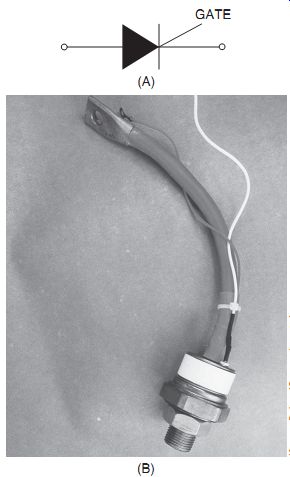
ill. 1 (A) Symbol for silicon-controlled rectifier (SCR). (B) Typical power
SCR.
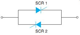
ill. 2 Inverse parallel SCRs per one phase.
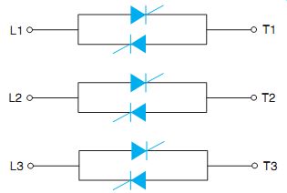
ill. 3 A three-phase SCR connection.
SOLID-STATE REDUCED VOLTAGE MOTOR STARTING
Although the details of how a solid-state reduced voltage starter works are complex, the basic principles are easy to grasp. Reduced volt age starting is accomplished by reducing the applied voltage to the motor, which allows the motor to start at a reduced current. The motor then accelerates to full speed at a lower torque level.
This technique reduces the high current inrush and the mechanical shock to driven equipment produced by across-the-line motor starting.
A solid-state, reduced voltage motor starter uses silicon controlled rectifiers (SCRs) for power control. SCRs are indicated by an arrowhead pointing in the direction of conventional current flow, ill. 1(A) and (B). SCRs block reverse current flow, like diodes. They also block forward current flow until they receive a turn-on signal, or gate pulse. Once an SCR is turned on (gated), it does not stop forward current flow until the current drops below a certain level. Full-wave control employs two SCRs in each phase by connecting them in inverse parallel. This connection is shown in ill. 2. In this connection scheme, SCR 1 controls the voltage when it's positive in the sine wave. SCR 2 controls the voltage when it's negative. For three-phase motors, the configuration shown in ill. 3 is used.
Control of current or acceleration time is achieved by gating the SCR at different times within the half-cycle. If the gate pulse is applied early in the half-cycle, the output is high. If the gate pulse is applied late in the half-cycle, only a small part of the waveform is passed through and the output is low. Thus, by controlling the SCR's output voltage, the motor acceleration characteristics can be controlled. These effective cult environmental conditions on electrical waveforms are shown in ill. 4. Feedback to the controller is supplied by current transformers in each phase on the line side of the starter, ill. 5. Should there be any abnormal changes in the line current through these current transformers, it's detected in the secondary circuit and fed back to a control circuit that adjusts for smooth and timed acceleration. Timed acceleration is also available from a tachometer generator that's attached to the motor shaft. This provides additional feedback to the controller, ill. 6.
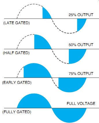
ill. 4 Outputs from differently gated SCRs.
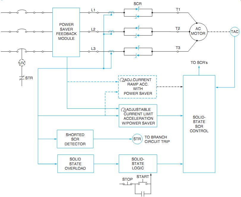
ill. 6 Block diagram of a reduced voltage starter.
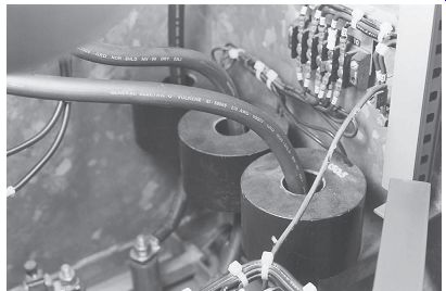
ill. 5 Current transformers used for feedback control and metering.
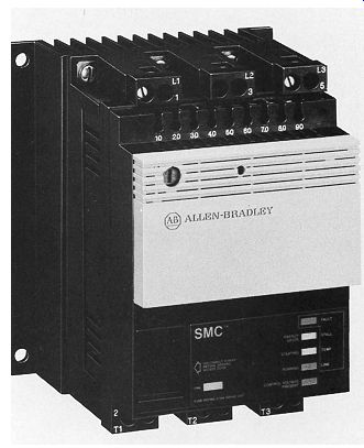
In addition, solid-state controllers contain solid-state overload relays that monitor both the controller and the motor for overcurrent conditions. Power-saving modules are available that detect idling or low-power periods of operation. The motor terminal voltage is then reduced to minimize electrical losses during these operating conditions. A solid-state, reduced voltage motor starter is shown in ill. 7.
- Motor and remote control terminal connections are made at a marked terminal block.
- Solid-state starters are available in many different types, incorporating different features.
As indicated in the elementary diagram in ill. 8, the starter includes both start and run contactors. The start contacts are in series with the SCRs. The run contacts are in parallel with the series combination of SCRs and the start contacts. When the starter is energized, the start contacts close. The motor acceleration is now controlled by phasing-on the SCRs.
When the motor reaches full speed, the run contacts close, connecting the motor directly across the line. At this point, the SCRs are turned off and the start contacts open. Thus, under full speed running conditions, the SCRs are out of the circuit. This eliminates SCR power dissipation during the run cycle.
With the starter in the de-energized state, the start contacts are open. This condition isolates the motor from the lines and the SCR circuits.
This open circuit condition protects against SCR misfiring or damage from overvoltage transients, or any electrical noise.
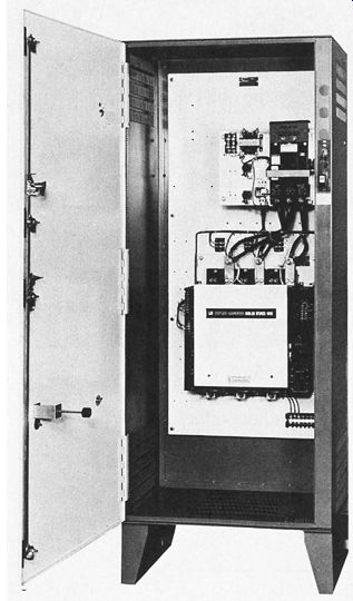
ill. 7 Solid-state, reduced voltage, three-phase starter. (E.g., from Eaton
Corporation)
ill. 8 Power circuit of SCRs with contactors.
SOLID-STATE CONTROL WITH EXISTING MAGNETIC DEVICES
In addition to the greater noise immunity provided by integrated electronic circuits, the logic functions (such as the relays, contactors, and starters previously described) include additional filtering and buffering to limit the effect of transient, electrical "spikes," which may exceed the safe voltage noise margin. Refer to ill. 9.
The integration and use of solid-state relays for industrial control poses several problems.
When they are used to operate electromagnetic equipment, replacing relays and contactors, they are susceptible to damage by these transient voltages. They cannot be used simply to replace a relay that fails because of contact arcing. Although the relay contacts may have reduced life, the solid-state relay will have no life unless adequately protected.
Surge suppressors are installed on magnetic device coils, such as relays, contactors, and motor starters. A voltage surge suppressor is shown in ill. 10. The leads of the suppressor are connected to the coil terminals. This further limits voltage noise and overvoltage spikes produced by the starter coil when the coil circuit's opened.
Reduced voltage solid-state starting units can be connected into existing magnetic starter installations for standard three-phase, AC induction motors as shown in ill. 11(A) and (B). This series incorporates an automatic energy controller with a reduced voltage starter to maximize the efficiency of the motor duty cycle. It can be used on any motor load or electrical system that benefits from reduced volt age soft start or where power can be saved.
Energy savings are accomplished by sensing the load and by reducing the voltage applied to the motor when it's running at less than full load conditions. The result is lower motor amperage and voltage (resulting in true kilowatt savings).
In addition to being a reduced voltage starter and energy saver, such a unit's also a motor monitor. It features adjustable current limit, phase loss detection, adjustable start, undervoltage protection, and no-voltage phase reversal. It also has a three-phase sensing overload current trip that acts on an inverse time function similar to a thermal overload relay. The unit also features SCR over temperature protection. ill. 12 shows a graph of the adjustable linear timed acceleration of a solid-state starter. This option starts the motor with a linear speed versus time acceleration. The starting is adjustable, thereby altering the current ramp. Some units may be adjusted for across-the-line starting as well. The current is still monitored so it does not exceed a preset level while starting. A locked rotor or overload would activate this preset trip level.
A motor-mounted tachometer output is used for feedback. Sometimes current transformers are used.
Nearly all of these functions are illuminated with electronic LEDs. LEDs are similar to pilot lights on push-button control stations. They are color-coded and serve as fault indicators and advise of condition status. The color coding of LEDs typically is as follows:
- GREEN Control voltage present; or running AMBER Starting; or energy saver RED Fault, including:
- Shorted SCR; phase loss. GREEN SCR over temperature AMBER. Stalled motor AMBER. This may be seen in ill. 13.
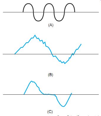
ill. 9 (A) Good computer-grade AC power. (B) Objectionable line noise. (C) Bad
temporary blackouts.
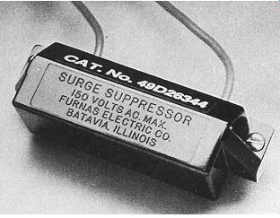
ill. 10 Voltage surge suppressor.(E.g., from Siemens Energy and Automation)
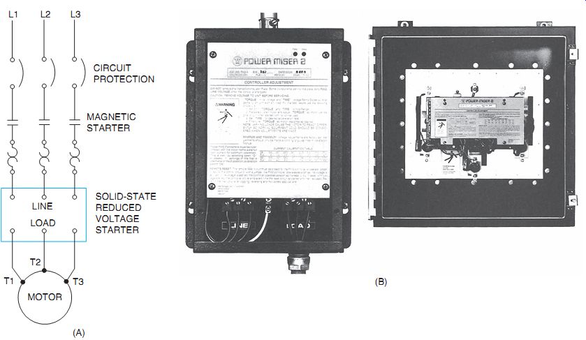
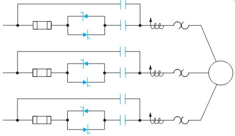
ill. 11 (A) Power circuit of a solid-state reduced voltage starter connected
into an existing motor installation. (B) This controller senses the motor load and feeds back the information, which is compared to a reference. As a result,
the voltage can be continuously changed to reduce the current and voltage under
light-load conditions. This energy saving feature results in lower power consumption and increased line power factor. (E.g., from Rockwell Automation)
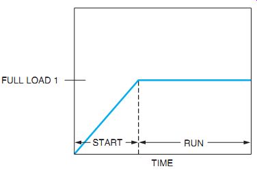
ill. 12 Smooth, stepless acceleration of an induction motor.
ill. 13 LEDs show the condition status of the motor starter. (E.g., from Allen
Bradley)
ENERGY SAVING
When a motor is lightly loaded or idling, it requires less magnetic flux. An energy-saving option will reduce the magnetic field strength by reducing the voltage to the motor during these periods. When the field is reduced, the motor will draw less current. The energy-saving option, including a microcomputer, is activated after the motor is up to speed. It automatically applies more voltage when the load increases.
APPLICATION
The solid-state reduced voltage starter is suited for starting most industrial loads, including fans, compressors, pumps, machine tools, and conveyors. This starter should provide complete control of the starting current and motor torque.
There are some general precautions, which should be considered in any application. Because of their greater complexity, failures will be more difficult to find. A more qualified maintenance person or an electronic technician may be required to service the equipment. Installation should be no more difficult than electro magnetic equipment, as long as the installer follows the wiring diagram and the terminal markings.
QUIZ:
1. List some advantages of solid-state control.
2. What element is the heart of the solid-state starter?
3. How is smooth acceleration achieved with a reduced voltage starter?
4. How are solid-state controllers connected into existing electromagnetic starters?
5. What are some additional features of a solid-state controller not commonly found on an electromagnetic starter?