AMAZON multi-meters discounts AMAZON oscilloscope discounts
Goals:
- • Describe the construction and operation of autotransformer starters.
- • Draw and interpret diagrams for autotransformer starters.
- • Connect squirrel cage motors to autotransformer starters.
- • Define what is meant by open transition and closed transition starting.
- • Troubleshoot electrical problems on autotransformer starters.
Autotransformer reduced voltage starters are similar to primary resistor starters in that they are used primarily with AC squirrel cage motors to limit the inrush current or to lessen the starting strain on driven machinery, ill. 1.
This type of starter uses autotransformers between the motor and the supply lines to reduce the motor starting voltage. Taps are provided on the autotransformer to permit the user to start the motor at approximately 50 percent, 65 percent, or 80 percent of line voltage.
Most motors are successfully started at 65 percent of line voltage. In situations where this value of voltage does not provide sufficient starting torque, the 80 percent tap is available.
If the 50 percent starting voltage creates excessive line drop to the motor, the 65 percent taps are available. This way of changing the starting voltage isn't usually available with other types of starters. The starting transformers are inductive loads; therefore, they momentarily affect the power factor. They are suitable for long starting periods, however.
Autotransformer Starters
To reduce the voltage across the motor terminals during the accelerating period, an autotransformer-type starter generally has two autotransformers connected in open delta. During the reduced voltage starting period, the motor is connected to the taps on the auto transformer. With the lower starting voltage, the motor draws less current and develops less torque than if it were connected to the line volt age, ill. 2.
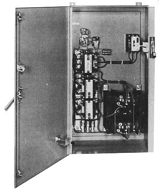
ill. 1 Reduced voltage autotransformer starter, size 3. (E.g., from Eaton Corporation)
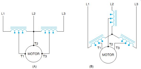
ill. 2 Power circuit connections showing two and three autotransformers used
for reduced voltage starting.
An adjustable time-delay relay controls the transfer from the reduced voltage condition to full voltage. A current-sensitive relay may be used to control the transfer to obtain current limiting acceleration.
ill. 2(A) shows the power circuit for starting the motor with two autotransformers.
ill. 2(B) shows the circuit for starting a motor with three autotransformers.
To understand the operation of the auto transformer starter more clearly, refer to the schematic diagram shown in ill. 3.When the start-button is pressed a circuit's completed to the coil of control relay CR, causing all CR contacts to close. One contact is employed to hold CR coil in the circuit when the start-button is released. Another completes a circuit to the coil of TR timer, which permits the timing sequence to begin. The CR contact connected in series with the normally closed TR contact sup plies power to the coil of S (start) contactor. The fourth CR contact permits power to be connect to R (run) contactor when the normally open timed TR contact closes.
When the coil of S contactor energizes, All S contacts change position. The normally closed S contact connected in series with R coil opens to prevent both S and R contactors from ever being energized at the same time. This is the same interlocking used with reversing starters.
When the S load contacts close the motor is connected to the power line through the auto transformers. The autotransformers supply 65% of the line voltage to the motor. This reduced voltage produces less in-rush current during starting and also reduces the starting torque of the motor.
When the time sequence for TR timer is completed, both TR contacts change position.
The normally closed TR contact opens and disconnects contactor S from the line causing all S contacts to return to their normal position.
The normally open TR contact closes and sup plies power through the now closed S contact to coil R. When contactor R energizes, all R contacts change position. The normally closed R contact connected in series with S coil opens to provide interlocking for the circuit. The R load contacts closed and connect the motor to full voltage.
When the stop-button is pressed, control relay CR de-energizes and opens all CR contacts. This disconnects all other control components from the power line and the circuit returns to its normal position. A wiring diagram for this circuit's shown in ill. 4.
Starting compensators (autotransformer starters) using a five-pole starting contactor are classified as open transition starters. The motor is disconnected momentarily from the line during the transfer from the start to the run conditions.
Closed transition connections are usually found on standard size 6 and larger starters. For the closed transition starter, ill. 5, the starting contactors consist of a three-pole (S2) and a two-pole (S1) contactor operating independently of each other. During the transfer from start to run, the two-pole contactor is open and the three-pole contactor remains closed. The motor continues to accelerate with the autotransformer serving as a reactor. With this type of starter, the motor isn't disconnected from the line during the transfer period. Thus, there is less line disturbance and a smoother acceleration.
The transformers are de-energized while in the running position. This is done to conserve electrical energy and to extend their life.
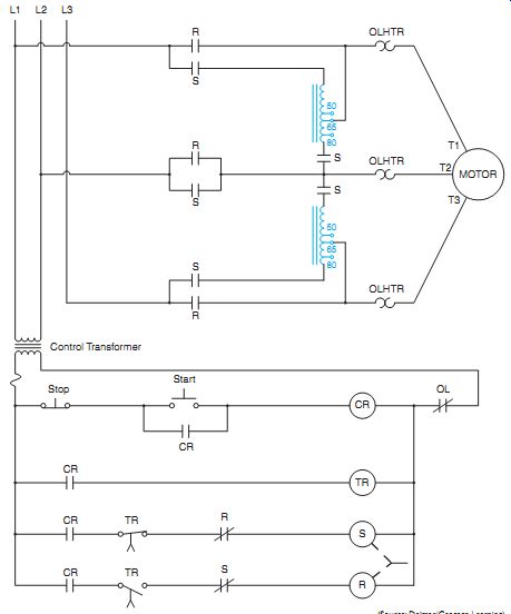
ill. 3 Schematic diagram of a basic autotransformer starter. Autotransformer
starters provide the greatest amount of starting torque per ampere of starting
current than any other type of reduced voltage starter.
The (CT) designations in ill. 5 indicate current transformers. These transformers are used on large motor starters to step down the current so that a conventional overload relay and heater size may be used. Magnetic overload relays are used on large reduced volt age starters also.
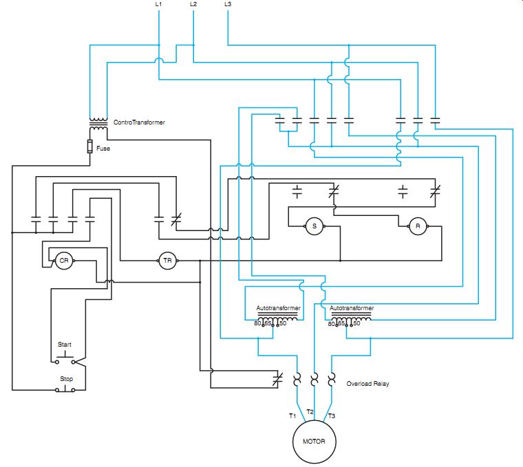
ill. 4 Wiring diagram of the circuit shown in ill. 3.
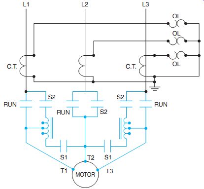
ill. 5 Closed transition (Korndorfer) connection.
QUIZ:
1. Why is it desirable to remove the autotransformers from the line when the motor reaches its rated speed?
2. What is meant by an "open transition" from start to run? Why is this condition objectionable at times when used with large horsepower motors?
3. Which of the following applies to an autotransformer starter with a five-pole starting contactor: open transition or closed transition? Locate in ill. 3.
4. How are reduced voltages obtained from autotransformer starters?
5. Assume the motor is running. What happens when the stop button is pressed and then the start button is pressed immediately?
6. What is a disadvantage of starting with autotransformer coils rather than with resistors?
7. What is one advantage of using an autotransformer starter?