AMAZON multi-meters discounts AMAZON oscilloscope discounts
Goals:
- • Describe the construction and operation of a part winding motor starter.
- • Draw and interpret diagrams for part winding motor starters.
- • List the advantages and disadvantages of two-step part winding starters.
- • Connect motors to part winding starters.
- • Describe the difference between part winding motors and dual voltage motors.
- • Troubleshoot part winding motor starters.
Part winding motors are similar in construction to standard squirrel cage motors. However, part winding motors have two identical windings that may be connected to the power supply in sequence to produce reduced starting current and reduced starting torque. These motor windings are intended to operate in parallel. Because only half of the windings are connected to the supply lines at startup, the method is described as part winding. (Many, but not all, dual-voltage, 230/460-volt motors are suitable for part winding starting at 230 volts.) By bringing out leads from each winding, the motor manufacturer enables the windings to be connected in parallel, external to the motor, with the starter (refer to ill. 13).
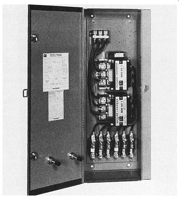
Part winding starters, ill. 1, are designed to be used with squirrel cage motors having two separate and parallel stator windings. In the part winding motor, these windings may be Y connected or delta connected, depending on the motor design.
Part winding starters are not suitable for use with delta-wound, dual-voltage motors.
Part winding motors are used to drive centrifugal loads such as fans, blowers, or centrifugal pumps. They are also used for other loads where a reduced starting torque is necessary.
This type of motor is also used where the full voltage starting current will produce objectionable voltage drops in the distribution feeders or where power company restrictions require a reduced starting current. Using a part winding starter to start a motor does not necessarily reduce the maximum starting current. Instead, incremental starting is obtained. Neither one of the two windings has the thermal capacity to operate alone for more than a few seconds. Therefore, unless the motor accelerates to practically full speed on the one winding, the TOTAL current drawn may approach that of line voltage starting.
This type of starting has many applications in air-conditioning systems. This is due to the increased capacity built into these systems and the necessity of limiting both the current and torque on starting.
TWO-STEP STARTING
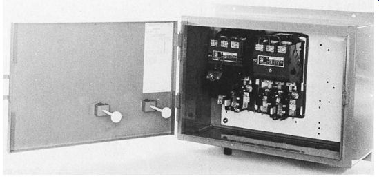
A part winding starter, ill. 2, has two main contactors. Each contactor controls one winding of the part winding motor. By energizing the contactors in sequence, first one motor winding is energized, and a short time later the second winding is connected in parallel with the first. As stated previously, the motor is started with one winding energized, giving rise to the name of the starting method part winding starting.
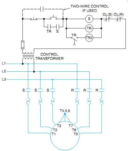
In a two-step part winding starter, ill. 3, pressing the start button energizes the start contactor (S). As a result, half of the motor windings are connected to the line and a timing relay (TR) is energized. After a time delay of approximately 5 seconds, the timer contacts (TR) close to energize the "run" contactor. This contactor connects the second half of the motor windings to the line in parallel with the first half of the windings. Note that the control circuit's maintained with an instantaneous normally open contact (TR) operated by the timing relay (TR) and the starting contact (S).
Pressing the stop button or tripping any overload relay disconnects both windings from the line. When starting on one winding, the motor draws approximately two-thirds of the normal locked rotor current and develops approximately one-half of the normal locked rotor torque.
A two-step part winding starter has certain obvious advantages:
1. It is less expensive. Most other starting methods require additional voltage reducing elements such as transformers, resistors, or reactors.
2. It uses only half-size contactors.
3. It provides closed transition starting.
The two-step part winding starter also has disadvantages:
1. The fixed starting torque is poor.
2. The starter is almost always an incremental start device. It is unsuitable for long starting, high-inertia, loads.

ill. 1 Part-winding-type, reduced current starter.

ill. 2 Part winding starter, two step. (E.g., Siemens Energy and Automation)

ill. 3 Line diagram of a two-step, part winding starter. When dual-voltage,
Y-connected motors are used on the lower voltage only, terminals T4, T5, and T6 are connected to form the center of the second Y.

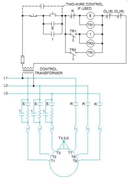
ill. 4 Elementary diagram of a three-step, part winding motor starter.
THREE-STEP STARTING
The thermal capacity of the motor limits the length of acceleration on the first winding to approximately 5 seconds, depending on the connected load. In many instances, the motor won't begin to accelerate until the second winding is connected.
Three-step starting is similar to two-step starting, except that when the first contactor closes, the first winding is connected to the line through a resistor in each phase, ill. 4.
After a time delay of approximately 2 seconds, this resistor is shunted out and the first winding is connected to the full voltage. After another time delay of about 2 seconds, the run contactor closes to connect both windings to the line voltage, ill. 5. The resistors are de signed to provide approximately 50 percent of the line voltage to the starting winding. Thus, the motor starts with three approximately equal increments of starting current.
OVERLOAD PROTECTION
Motor overload protection is provided by six overload relays, three in each motor winding. Be cause the windings are identical, each winding should have the same full-load current. In addition, each phase of the start winding will carry a current identical to that of the corresponding phase in the run winding. Thus, if three overload relays are connected in three phases in the run winding and three other relays are connected in three different phases in the start winding, then the effect of full three-phase protection is obtained.
When selecting heater elements for the over load relays, the electrician should remember that each of the relays carries only half of the motor current. The elements, therefore, must be selected on the basis of one-half of the full-load current of the motor, unless otherwise specified.
The current requirements in part winding starters permit the use of smaller contactors with smaller overload elements. As a result, because the starting fuses must be proportionally smaller to protect these elements, dual-element fuses are required. When in doubt regarding installation and protection problems, local electrical codes and ordinances should always be consulted.
QUIZ:
1. How can a 230/460-volt motor be used as a part winding motor?
2. Which voltage may be applied to a 230/460-volt motor if used with a part winding starter? Why?
3. If the nameplate of a dual-voltage motor connected to a part winding starter reads 15/30 amperes, which amperage value is used as the basis for the selection of the overload heating elements?
4. If a timing relay fails to cut in the run starter, what percentage of the full-load current can the motor carry safely?
5. When starting on one winding, a motor draws approximately what percentage of the normal locked rotor current?
6. How is a third step gained in part winding starting?
7. Who determines the compliance of an installation to valid electrical codes with regard to adequate overload or starting and short-circuit protection?