AMAZON multi-meters discounts AMAZON oscilloscope discounts
Goals:
- • State why reduced current starting is important.
- • Describe the construction and operation of primary resistor starters.
- • Interpret and draw diagrams for primary resistor starters.
- • Connect squirrel cage motors to primary resistor starters.
- • Troubleshoot electrical problems on primary resistor starters.
PRIMARY RESISTOR-TYPE STARTERS
A simple and common method of starting a motor at reduced voltage is used in primary resistor-type starters. In this method, a resistor is connected in series in the lines to the motor, ill. 1.Thus, there is a voltage drop across the resistors and the voltage is reduced at the motor terminals. Reduced motor starting speed and current are the result. As the motor accelerates, the current through the resistor decreases, reducing the voltage drop (E = IR) and increasing the voltage across the motor terminals. A smooth acceleration is obtained with gradually increasing torque and voltage.
The resistance is disconnected when the motor reaches a certain speed. The motor is then connected to run on full-line voltage, ill. 2. The introduction and removal of resistance in the motor starting circuit may be accomplished manually or automatically.
Primary resistor starters are used to start squirrel cage motors in situations where limited torque is required to prevent damage to driven machinery. These starters are also used with limited current inrush to prevent excessive power line disturbances.
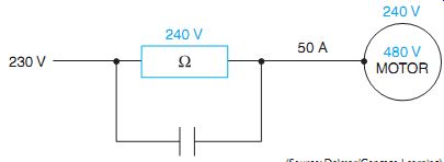
ill. 1 Reduced voltage starting.
It is desirable to limit the starting current in the following cases:
1. When the power system does not have the capacity for full-voltage starting
2. When full-voltage starting may cause serious line disturbances, such as in lighting circuits, electronic circuits, the simultaneous starting of many motors, or when the motor is distant from the incoming power supply
In these situations, reduced voltage starters may be recommended for motors with ratings as small as 5 horsepower.
Reduced voltage starting must be used for driving machinery, which must not be subjected to a sudden high starting torque and the shock of sudden acceleration. Among typical applications are those where belt drives may slip or where large gears, fan blades, or couplings may be damaged by sudden starts.
Automatic primary resistor starters may use one or more than one step of acceleration, depending on the size of the motor being controlled. These starters provide smooth acceleration with out the line current surges normally experienced when switching autotransformer types of reduced voltage starters.
Primary resistor starters provide closed transition starting. This means the motor is never disconnected from the line from the moment it's first connected until the motor is operating at full line voltage. This feature may be important in wiring systems sensitive to voltage changes.
Primary resistor starters do consume energy, with the energy being dissipated as heat. However, the motor starts at a much higher power factor than with other starting methods.
Special starters are required for very high inertia loads with long acceleration periods or where power companies require that current surges be limited to specific increments at stated intervals.
ill. 2 The curves illustrate how a primary resistance starter reduces the starting current of a 10-hp, 230-volt motor under three different load conditions.
Curve I is at a light load and Curve II is at a heavy load. In either case, the running switch closes after 3 seconds.
With a heavy load, an increase in the starting time reduces the second current inrush; the motor will reach a higher speed before it's connected to full line voltage.
In Curve III the motor cannot start on the current allowed through the resistance; it comes up to speed only after connection to full line voltage.
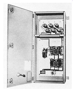
ill. 3 Reduced voltage, primary resistance-starter.
Resistors are in the top ventilated system. (Eaton Corporation)
Primary Resistor-Type Reduced Voltage Starter
ill. 3 and ill. 4 illustrate an automatic, primary-resistor-type reduced voltage starter with two steps of acceleration. The circuit consists of resistors connected in series with a three-phase squirrel cage induction motor.
A control transformer is used to reduce the line voltage, supplying the motor to 120 volts to operate the control circuit. When the start but ton is pressed, a circuit's completed to the coil of M starter, causing all M contacts to close. The three M load contacts connect the motor to the line through the series resistors. The three resistors limit the amount of current supplied to the motor. Current flowing through the resistors produces a voltage drop across them. The resistor voltage drop causes a voltage drop across the motor terminals also. The motor starts with reduced voltage applied to it. As the motor accelerates, the current flow to the motor decreases, causing less voltage drop across the resistors and more voltage to be applied to the motor.
When M coil is energized, the two M auxiliary contacts also close. One is used as a holding contact, and the other energizes the coil of on delay timer TR. At the end of the timing period, TR contacts close and energize the coil of S contactor. When S coil energizes, the S load contacts connected in parallel with the resistors close and short circuit the resistors. The motor is now connected directly to the power line.
When the stop button is pressed, M starter coil de-energizes, causing all M contacts to return to their open position. The three M load contacts open and disconnect the motor from the power line. The M auxiliary contact connected in series with TR coil opens and causes on-delay timer TR to de-energize. This causes TR contact to open and de-energize S coil. When the three S load contacts reopen, the circuit's back in its original de-energized state.
For maximum operating efficiency, push buttons and other pilot devices are usually located on the driven machine or in easy reach of the operator. The starter is located near the motor to keep the power circuit wiring as short as possible. Only three small connecting wires are necessary between the starter and the pilot devices. A motor can be operated from any of several remote locations if a number of push buttons or pilot switches are used with one magnetic starter, such as on a conveyor system.
AC primary resistor starters are available for use on single-phase and three-phase reversing operations. They are also available with multi points of acceleration.
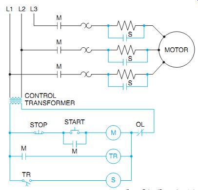
ill. 4 Line diagram of primary resistor starter with two-step acceleration.
Four-Point Resistor Starter
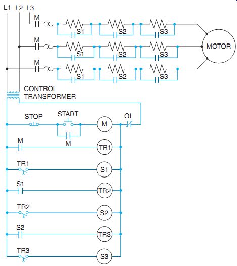
Ill. 5 Schematic diagram of a four-point primary resistor starter.
ill. 5 illustrates a resistor starter with four points of acceleration. When the start but ton is pressed, M coil energizes and causes all M contacts to close. The three M load contacts connect the motor to the power line through the resistors connected in series with the motor. At this point, the resistors provide maximum volt age drop and current limit to the motor. The motor is now in its first or lowest speed. When M auxiliary contact connected in series with TR1 on-delay timer coil closed, timer TR1 began its time sequence. At the end of its time sequence, TR1 contact closes and energizes the coil of S1 contactor coil. This causes the three S1 load contacts to close and shunt out the first set of resistors in the motor circuit. Motor current is now limited by two series resistors instead of three.
More current is supplied to the motor, causing it to accelerate. When S1 coil was energized, S1 auxiliary contact closed and energized the coil of on-delay timer TR2. After the preset time for TR2 expires, TR2 contact will close and energize the coil of S2 contactor. S2 load contacts close and shunt out the second set of resistors. The motor now has only one set of resistors connected in series with it. The motor advances to third speed. The S2 auxiliary contact connected in series with the coil of TR3 on-delay time closes and energizes TR3 coil. At the end of its time sequence, contact TR3 closes and energizes the coil of S3 contactor. All S3 load contacts close and shunt out the last of the resistors connected in series with the motor. The motor is now connected directly to the power line and operates in its fourth or highest speed.
ill. 6 shows two types of resistor banks used to start small motors. The resistors, shown in ill. 6(A), consist of resistance wire wound around porcelain bases and imbedded in refractory cement. The other resistor, ill. 6(B), has a ribbon-type construction and is used on larger motor starters. This type of resistor consists of an alloy ribbon formed in a zig-zag shape. The formed ribbon is supported between porcelain blocks, which have recesses for each bend of the ribbon. The ribbons are not stressed and don't have a reduced cross section, because they are bent on the flat and not on the edge. Any number of units can be combined vertically or horizontally in series or in parallel.
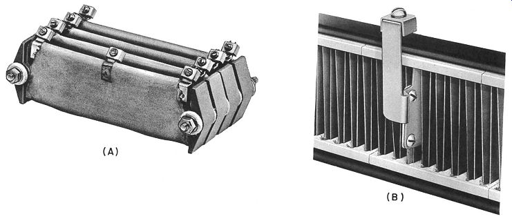
ill. 6 Resistors used in primary resistor-type starters. Ribbon resistor is
used with larger starter. (Schneider Electric)
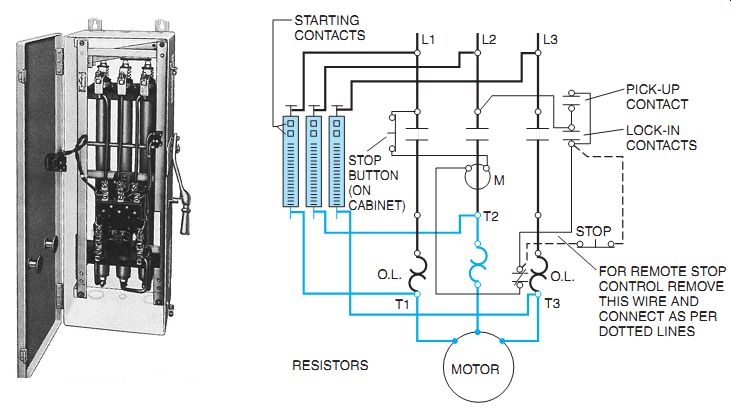
ill. 7 Manual resistance starter with "carbon pile" resistors. (Rockwell
Automation)
Some starters have graphite compression disk resistors and are used for starting polyphase squirrel cage motors, ill. 7.
A primary resistance-type starter has the following features:
++ simple construction
++ low initial cost
++ low maintenance
++ smooth acceleration in operation
++ continuous connection of the motor to the line during the starting period
++ a high power factor
These starters shouldn't be used for starting very heavy loads because of their low starting torque. These starters are said to have a low starting economy because the starting resistors dissipate electrical energy.
QUIZ:
1. What is the purpose of inserting resistance in the stator circuit during starting?
2. Why is the power not interrupted when the motor makes the transition from start to run?
3. If the starter is to function properly and a timing relay is used, where must the coil of the relay be connected?
4. How may additional steps of acceleration be added?
5. What is meant by the low or poor starting economy of a primary resistor starter?
6. How does this starter provide smooth acceleration and a gradual increase of torque?