AMAZON multi-meters discounts AMAZON oscilloscope discounts
Goals:
- • Describe the most important factors to consider when selecting motor starting equipment.
- • State why reduced current starting is important.
- • Describe typical starting methods.
- • Identify squirrel cage induction motors.
- • Describe how a squirrel cage motor functions.
There are two reasons for the use of reduced voltage starting:
1. To reduce the high starting current drawn by the motor
2. To reduce the starting torque provided by the motor
The simplicity, ruggedness, and reliability of squirrel cage induction motors have made them the standard choice for AC, all-purpose, constant-speed motor applications. Several types of motors are available; therefore, various kinds of starting methods and control equipment are also obtainable.
THE MOTOR
The Revolving Field
The squirrel cage motor consists of a frame, a stator, and a rotor. The stator, or stationary portion, carries the stator windings, ill. 1 (center). The rotor is a rotating member, ill. 1 (bottom) that's constructed of steel laminations mounted rigidly on the motor shaft.
The rotor winding consists of many copper, or aluminum, bars fitted into slots in the rotor. The bars are connected at each end by a closed continuous ring. The assembly of the rotor bars and end rings resembles a squirrel cage. This similarity gives the motor its name, squirrel cage motor.
For a three-phase motor, the stator frame has three windings. The stator for a squirrel cage motor never has fewer than two poles. The stator windings are connected to the power source.
When a 60-hertz current flows in the stator winding, a magnetic field is produced. Because of the three-phase alternating current and the displacement of each phase winding, this field circles the rotor at a speed equal to the number of revolutions per minute (r/min or rpm) divided by the number of pairs of stator poles. Therefore, on 60 hertz, a motor having one pair of two poles will run at 3600 r/min; a four-pole motor (two pairs of two poles each) will run at 1800 r/min (3600/2). The revolving stator magnetic field induces current in the short-circuited rotor bars.
The induced current in the squirrel cage then has a magnetic field of its own. The two fields inter act, with the rotor field following the stator rotating field, thereby establishing a torque on the motor shaft. The current induced has its largest value when the rotor is at a standstill.
The current then decreases as the motor comes up to speed. In designing motors for specific applications, changing the resistance and reactance of the rotor will alter the characteristics of the motor. For any one rotor design, however, the characteristics are fixed. There are no external connections to the rotor. A cutaway view of an assembled squirrel cage motor is shown in ill. 2.
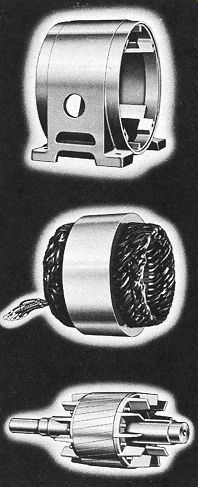
ill. 1 Squirrel cage induction motor frame, stator, and rotor. Note the
cooling blades on the rotor. (E.g., from Emerson Motors)
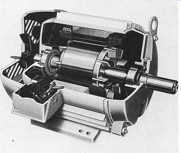
ill. 2 Cutaway view of a squirrel cage motor. (E.g., from Emerson Motors)
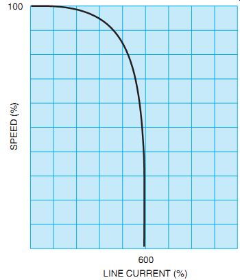
ill. 3 Induction motor current at various speeds.
Locked Rotor Currents
The locked rotor current and the resulting torque are factors that determine if the motor can be connected across the line or if the cur rent must be reduced to obtain the required performance. Locked rotor currents for different motor types vary from 2½ to 10 times the full-load current of the motor. Some motors, however, have even higher inrush currents.
The Induction Motor at Start
ill. 3 illustrates the behavior of the current taken by an induction motor at various speeds. First, note that the starting current is high compared with the running current. In addition, the starting current remains fairly constant at this high value as the motor speed increases. The current then drops sharply as the motor approaches its full rated speed. Because the motor heating rate is a function of I^2 (copper loss), this rate is high during acceleration. For most of the acceleration period, the motor can be considered to be in the locked condition.
No-Load Rotor Speed
The induced current in the rotor gives rise to magnetic forces, which cause the rotor to turn in the direction of rotation of the stator field. The motor accelerates until the necessary speed is reached to overcome windage and friction losses. This speed is referred to as the no-load speed. The motor never reaches synchronous speed because a current won't be induced in the rotor under these conditions and thus the motor won't produce a torque. Torque refers to the twisting or turning of the motor shaft. (The rotor bars of the squirrel cage must be cut by the rotating magnetic AC field to produce a torque.)
Speed Under Load
As the rotor slows down under load, the speed adjusts itself to the point where the forces exerted by the magnetic field on the rotor are sufficient to overcome the torque required by the load. Slip is the term given to the difference between the speed of the magnetic field and the speed of the rotor.
The slip necessary to carry the full load depends on the characteristics of the motor. In general, the following situations are true:
1. The higher the inrush current, the lower the slip at which the motor can carry full load, and the higher the efficiency.
2. The lower the value of inrush current, the higher the slip at which the motor can carry full load, and the lower the efficiency.
An increase in line voltage causes a decrease in the slip, and a decrease in line voltage causes an increase in the slip. In either case, sufficient current is induced in the rotor to carry the load.
A decrease in the line voltage causes an increase in the heating of the motor. An increase in the line voltage decreases the heating. In other words, the motor can carry a larger load. The slip at rated load may vary from 3 percent to 20 percent for different types of motors.
Variation of Torque Requirements
Different loads have different torque requirements. This must be kept in mind when considering the starting torque required and the rate of acceleration most desirable for the load. In general, a number of motors will satisfy the load requirements of an installation under nor mal running conditions. However, it may be more difficult to use a motor that will perform satisfactorily during both starting and running.
Often, it's necessary to decide which is the more important factor to consider for a particular application. E.g., a motor may be selected to give the best starting performance, but there may be a sacrifice in the running efficiency. In another case, to obtain a high running efficiency, it may be necessary to use a motor with a high-current inrush. For these and other examples, the selection of the proper starter to overcome the objectionable features is an important consideration in view of the high cost of energy today.
The machine to which the motor is connected may be started at no load, normal load, or over load conditions. Many industrial applications require that the machine be started when it's not loaded. Thus, the only torque required is that necessary to overcome the inertia of the machine.
Other applications may require that the motor be started while the machine it's driving is subjected to the same load it handles during normal running. In this instance, the starting requirements include the ability to overcome both the normal load and the starting inertia.
Important factors in providing the proper starting equipment include using a starter that satisfies the horsepower rating of the motor, and connecting the motor directly across the line. Another factor is that the motor itself must meet the torque requirements of the industrial application. Actually, the starting equipment may be selected to provide adequate control of the torque after the motor is selected.
Controlling Torque
The most common method of starting a polyphase, squirrel cage induction motor is to connect the motor directly to the plant distribution system at full voltage. In this case a manual or a magnetic starter is used. From the standpoint of the motor itself, this is a perfectly acceptable practice. As a matter of fact, it's probably the most desirable method of starting this type of motor.
Overload protective devices have reached such a degree of reliability that the motor is given every opportunity to make a safe start.
The application of a reduced voltage to a motor in an attempt to prevent overheating during acceleration is generally wasted effort. The accelerating time will increase and correctly sized overload elements may still trip.
Reduced voltage starting minimizes the shock on the driven machine by reducing the starting torque of the motor. A high torque, applied suddenly, with full-voltage starting, may cause belts to slip and wear or may damage gears, chains, or couplings. The material being processed, or conveyed, may be damaged by the suddenly applied jerk of high torque. By reducing the starting voltage, or current, at the motor terminals, the starting torque is decreased.
Reduced Voltage, Reduced
Current, Reduced Torque
The category of reduced voltage methods generally includes all starting methods that deviate from standard, line voltage starting.
Not all of these starting schemes reduce the voltage at the motor terminals. Even reduced voltage starters reduce the voltage only to achieve either the reduction of line current or the reduction of starting torque. The reduction of line current is the most commonly desired result.
You should note one important point: When the voltage is reduced to start a motor, the cur rent is also reduced, and so is the torque that the machine can deliver. Regardless of the desired result (either reduced current or reduced torque), remember that the other will always follow.
If this fact is kept in mind, it's apparent that a motor that won't start a load on full voltage cannot start that same load at reduced voltage or reduced current conditions. Any attempt to use a reduced voltage or current scheme won't be successful in accelerating troublesome loads. The very process of reducing the voltage and current will further reduce the available starting torque.
Need for Reduced Current Starting
The most common function of reduced volt age starting devices is to reduce, or in some way modify, the starting current of an induction motor. In other words, the rate of change of the starting current is confined to prescribed limits, or there is a predetermined current-time picture that the motor presents to the supply wiring network.
A current time picture for an entire area is maintained and regulated by the public power utility serving the area. The power company attempts to maintain a reasonably constant voltage at the points of supply so that lamp flicker won't be noticeable. The success of the power company in this attempt depends on the generating capacity to the area; transformer and line-loading conditions and adequacies; and the automatic voltage regulating equipment in use. Voltage regulation also depends on the sudden demands imposed on the supply facilities by residential, commercial, and industrial customers. Transient overloading of the power supply may be caused by (1) sudden high surges of reactive current from large motors on starting, (2) pulsations in current taken by electrical machinery driving reciprocating compressors and similar machinery, (3) the impulse demands of industrial x-ray equipment, and (4) the variable power factor of electric furnaces.
All of these demands are capable of producing voltage fluctuations.
Therefore, each of these particularly difficult loads is regulated in some way by the power utility. The utility requires the use of some form of reduced voltage, reduced current method and helps its customers determine the best method.
Power company rules and regulations vary between individual companies and the areas served. The following list gives some commonly applied regulations. (All of the possible restrictions on energy usage are not given.) An installation may be governed by just one of these restrictions, or two or more rules may be combined. Regulations include
1. A maximum number of starting amperes, either per horsepower or per motor.
2. A maximum horsepower for line starting.
A limit in percent of full-load current is set for anything above this value.
3. A maximum current in amperes for particular feeder size. It is up to the user to determine if the motor will conform to the power company requirements.
4. A maximum rate of change of line current taken by the motor; for example, 200 amperes per half-second.
It should be apparent that it's very important for the electrician to understand the behavior of an induction motor during the start-up and acceleration periods. Such an understanding enables you to select the proper starting method to conform to local power company regulations. Even though several starting methods may appear to be appropriate, a careful examination of the specific application will usually indicate the one best method for motor starting.
TYPICAL STARTING METHODS
The most common methods of starting polyphase squirrel cage motors include:
++ Full-voltage starting: A hand-operated or automatic starting switch throws the motor directly across the line.
++ Primary-resistance starting: A resistance unit connected in series with the stator reduces the starting current.
++ Autotransformer or compensator starting:
Manual or automatic switching between the taps of the autotransformer gives reduced voltage starting.
++ Impedance starting: Reactors are used in series with the motor.
++ Star-delta starting: The stator of the motor is star connected for starting and delta connected for running.
++ Part winding starting: The stator windings of the motor are made up of two or more circuits; the individual circuits are connected to the line in series for starting and in parallel for normal operation.
Some solid-state motor starters include many desirable features such as a power saver. This reduces motor voltage under light or no-load conditions to keep motors cooler and save energy. Starting currents are adjustable and contain adjustable cur rent sensors for overload protection. They provide for reduced voltage and gradual starting of motors.
++ Solid-state electronic control: Control of current or acceleration time is achieved by gating silicon controlled rectifiers with the AC half cycle.
Of these methods, the two most fundamental ways of starting squirrel cage motors are full-voltage starting and reduced voltage starting. Once again, full voltage starting can be used where the driven load can stand the shock of starting and objectionable line disturbances are not created. Reduced voltage starting may be required if the starting torque must be applied gradually or if the starting current produces objectionable line disturbances.
QUIZ:
1. List five commonly used starting methods.
2. When can full-voltage starting be used?
3. Name the simplest, most rugged, and reliable AC motor. Describe how it operates.
4. Describe the term slip.
5. When the voltage is reduced to start a motor, what happens to the:
a. torque?
b. current?
6. Why is it more advisable to start some machines at reduced torque?