AMAZON multi-meters discounts AMAZON oscilloscope discounts
LEARNING GOALS:
• Describe the basic sequence of operations for a three-wire control circuit.
• Describe the basic sequence of operations for a separate control circuit.
• List the advantages of each type of circuit.
• Connect three-wire and separate control circuits.
• Connect pilot indicating lights.
• Connect an alarm silencing circuit.
• Read and draw three-wire and separate control circuits.
THREE-WIRE CONTROLS
A three-wire control circuit uses momentary contact, start-stop stations, and a holding circuit interlock connected in parallel with the start button to maintain the circuit.
In general, three-wire devices are connected, as shown in ill. 1. Although the arrangement of the various parts may vary from one manufacturer's switch to another, the basic circuit remains the same.
The sequence of operation for this circuit's as follows: When the start button is pushed, the circuit's completed through the coil (shown as M) and the contacts at M close. The power circuit contacts to the motor also close (not shown).
When the start button is released, the holding contact on M keeps this auxiliary contact on.
When the starter is used in this manner, it's said to be "maintaining" or "sealing." With the holding contact closed, the circuit's still complete through the coil. If the stop button is pushed, the circuit's broken, the coil loses its energy, and the contacts at M open. When the stop button is released, the circuit remains open because both the holding contact and the start button are open. The start button must be pushed again to complete the circuit. The operation of the overload protection opens the control circuit, resulting in the same effect.
If the supply voltage fails, the circuit's de energized. When the supply voltage returns, the circuit remains open until the start button is pushed again. This arrangement is called no-voltage protection and protects both the operator and the equipment.
The push-button station wiring diagram, ill. 1(B), represents the physical station.
It shows the relative positions of the units, the internal wiring, and the connections to the starter. The wires to the terminals are labeled 1, 2, and 3 (giving rise to the name "three-wire control"). For similar diagrams, review ill 4-2 and ill 5-5. A pilot light or alarm can be added to this circuit to indicate when the motor is running (ill. 2). For this case, the pilot light is connected between control terminal 3 and line 2. Normally open auxiliary contacts are used to switch the pilot light on and off.
When the motor is running, these contacts are closed; when the motor is stopped, the contacts are open and the pilot light is off. Except for this modification, the circuit's a basic three-wire, push-button control circuit.
PUSH-TO-TEST PILOT LIGHTS
It is necessary to restart a motor after it has been stopped by a three-wire control circuit with low-voltage protection. An indicating lamp is often used to signal this when a motor stops so that it can be restarted after the problem causing the stoppage is cleared. Because pilot lights are an important component in such cases, they are tested frequently to ensure operation. Push to-test pilot lights show immediately if a circuit's off or if the lamp is burned out. Part of ill. 2 shows the schematic wiring for such a circuit. The three-wire motor starter control circuit's wired as usual. Note that the pilot lamp is energized from terminal 3 down to C, through a normally closed push button to L2. To test, the lamp is pushed, opening the circuit at C and closing it across L1.With a push-button arrangement, the lamp is tested directly across lines 1 and 2.
ALARM SILENCING CIRCUIT
Sirens, horns, and loud buzzers are also used in production systems to call attention to malfunctions. The problem is acknowledged by attempts to silence this "noise pollution.” A typical circuit's shown in ill. 3.Assume a high pressure in an industrial system is dangerous to continue.
Such a condition will close a pressure switch.
When this switch closes, the alarm is sounded through normally closed contact S. In addition, the red indicating lamp lights. When alerted, maintenance personnel can silence the alarm by depressing the off push button. The red light continues to silently announce the problem until it's cleared. After the pressure switch opens, the alarm system can be reactivated by pressing the on button. There are virtually unlimited control circuits using the three-wire system.
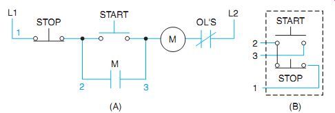
ill. 1 Basic three-wire control circuit.
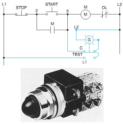
ill. 2 Push-to-test oil-tight push button. (Schneider Electric)
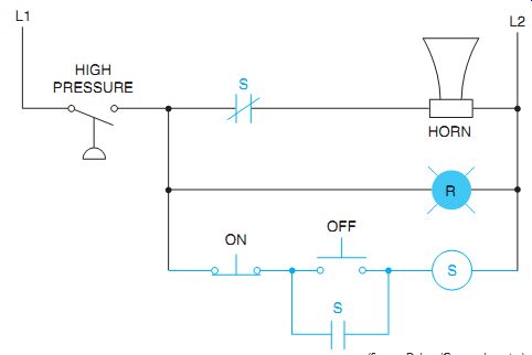
ill. 3 Alarm silencing circuit.
SEPARATE CONTROL
It is sometimes desirable to operate push buttons or other control devices at some voltage lower than the motor voltage. In the control system for such a case, a separate source-such as an isolating transformer or an independent voltage supply-provides the power to the control circuit. This independent voltage is separate from the main power supply for the motor.
One form of separate control is shown in ill. 4.This is an elementary diagram of a cooling circuit for a commercial air-conditioning installation. When the thermostat calls for cooling, the compressor motor starter coil (shown as M) is energized through the stepdown isolating transformer. When coil M is energized, power contacts in the 240-volt circuit close to start the refrigeration compressor motor. Because the control circuit's separated from the power circuit by the isolating control transformer, there is no electrical connection between the two circuits. For this reason, the wire jumper attached to L2 on a starter should be removed for different voltages. However, the overload relay control contact must be included in the separate control wiring. The maintenance technician must also ensure that the control transformer voltages match the voltages used and that the proper connections are made.
Another example of separate control is the thermal relay shown in ill. 5. This control consists of a line to a low-voltage transformer, two low-voltage heaters (H), and two normally open line voltage contacts. When heat is required, the thermostat closes the 24-volt circuit to the bimetallic heaters. In seconds, the action of the heaters causes the normally open contacts (H) to close on the 120-volt side. As a result, contactor coils M1 and M2 are energized.
When the M1 and M2 contactors close, they energize the three-phase heaters on 480 volts, ill. 5(B). Circulating blowers (not shown) will start when the heaters are energized. Three separate voltages are shown in ill. 5. Both two-wire and three-wire controls are used with separate controls.
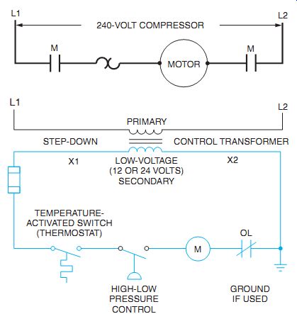
ill. 4 Separate control used in air-conditioning cooling circuit. THREE PHASE
480 VOLTS
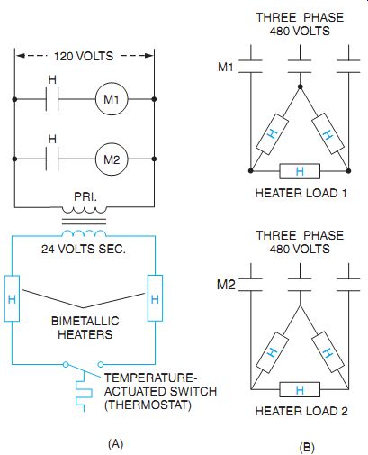
ill. 5 Separate control used in air-conditioning heating circuit.
QUIZ:
1. Draw a control circuit with no-voltage protection. Describe how this method of wiring protects the machine operator.
2. In the conduit layout shown in ill. 6, determine how many wires are contained in each conduit between each piece of equipment. Identify each wire with a proper terminal marking, as shown in the example, above the disconnect switch.