AMAZON multi-meters discounts AMAZON oscilloscope discounts
Goals:
• State the purpose of hand-off automatic controls.
• Connect hand-off automatic controls.
• Read and draw diagrams using hand-off automatic controls.
Hand-off automatic switches are used to select the function of a motor controller either manually or automatically. This selector switch may be a separate unit or built into the starter enclosure cover. A typical control circuit using a single-break selector switch is shown in ill. 1.
With the switch turned to the HAND (manual) position, coil (M) is energized all the time and the motor runs continuously. In the OFF position, the motor does not run at all. In the AUTO position, the motor runs whenever the two-wire control device is closed. An operator does not need to be present. The control device may be a pressure switch, limit switch, thermo stat, or other two-wire control pilot device.
The heavy-duty, three-position double-break selector switch shown in ill. 2 is also used for manual and automatic control. When the switch is turned to HAND, the coil is energized, bypassing the automatic control device in the AUTO position.
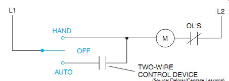
ill. 1 Standard-duty, three-position selector switch in control circuit.
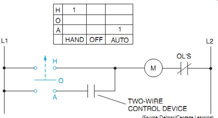
ill. 2 Diagram of a heavy-duty, three-position selector switch in control
circuit.
QUIZ:
1. A selector switch and two-wire pilot device cannot be used to control a large motor directly but rather must be connected to a magnetic starter. Explain why this is true.
2. Determine the minimum number of wires in each conduit shown in ill. 3.
3. The circuit shown in ill. 4(A) is used to control the operation of a motor.
The motor can be operated manually or it can be operated automatically by a pres sure switch. The circuit components necessary to construct this circuit are shown in ill. 4(B). In ill. 4(B), dashed lines on the starter indicate factory connections. It is also assumed that the output side of the load contacts are connected to the input side of the overload heaters. Using the schematic in ill. 4(A), draw lines to connect the components in ill. 4(B).