AMAZON multi-meters discounts AMAZON oscilloscope discounts
GOALS:
• List the advantages of two-wire controls.
• Connect two-wire devices to motor starters.
• Read and draw simple diagrams for two-wire controls.
A two-wire control may be a toggle switch, pres sure switch, float switch, limit switch, thermo stat, or any other type of switch having definite on and off positions. As indicated in Unit 16, de vices of this type are generally designed to handle small currents. Two-wire control devices won't carry sufficient current to operate large motors. In addition, 230-volt motors and three-phase motors require more contacts than the one contact usually provided on two-wire devices.
Two-wire controls may be connected to operating coils of magnetic switches, as shown in ill. 1.When the switch is closed, the control circuit's completed through the coil (M).
When the coil is energized, it closes the contacts at M and runs the motor. When the switch is opened, the coil is de-energized and the contacts open to stop the motor. In the case of an over load, the thermal heaters open the overload contacts in the control circuit and de-energize the coil, thus stopping the motor. Two-wire control provides no-voltage (or low-voltage) release. When the starter is wired, as shown in ill. 1, it will operate automatically in response to the control device. A human opera tor isn't required. The control maintaining contact 2-3 (shown in the wiring diagram) is furnished with the starter. However, this contact isn't used in two-wire control. For simplicity, this contact is omitted from the two-wire elementary diagram. The motor starter in ill. 1(A) is a line voltage, or across-the-line, starter (described in Unit 3).
The circuit shown in ill. 1 employs the use of line voltage controls. This simply means that the control components must be rated to operate on the voltage of the line sup plying power to the motor. If the power line is 480 volts, the contactor coil must be rated at 480 volts and the contacts of the two-wire control device and the overload relay must be capable of interrupting this voltage. Two-wire controls often use a control transformer to reduce the control voltage to a lower value, ill. 2. Typical control voltages are 120 and 24 volts. Control systems that operate on 24 volts are often used in hazardous areas. The NEC permits the use of intrinsically safe systems in areas that contain hazardous vapors.
Intrinsically safe systems cannot provide enough energy to ignite the surrounding atmosphere. These systems are much more cost effective than installing explosion proof fixtures.
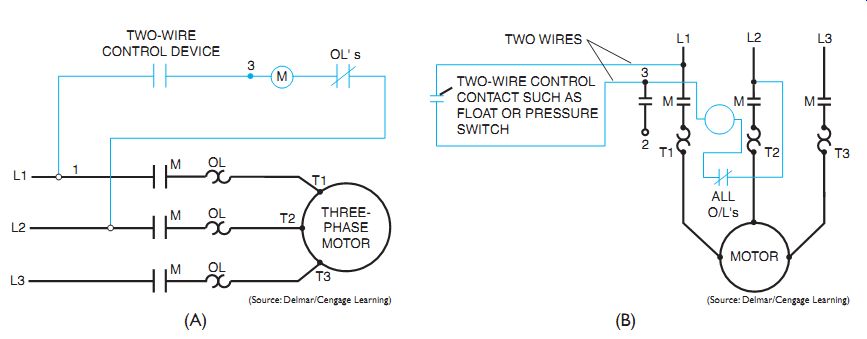
ill. 1 (A) Basic two-wire control circuit-elementary diagram. (B) Basic
two-wire control circuit-wiring diagram.
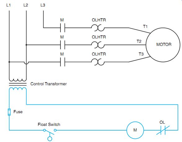
ill. 2 A control transformer reduces the voltage of the control circuit.
QUIZ:
1. What are some advantages of the use of two-wire control?
2. How many wires are required for a two-wire control device?
3. In the conduit diagram shown in ill. 3, determine how many wires are in each conduit between each piece of equipment. Identify each wire terminal connection and the quantity of wires, as shown in the example, above the disconnect switch.
4. Draw an elementary diagram of a pressure switch controlling a motor starter only.
5. What is an intrinsically safe system?
6. What is the most common control voltage used in an intrinsically safe system?