AMAZON multi-meters discounts AMAZON oscilloscope discounts
GOALS:
- • Tell how contactors differ from relays and motor starters.
- • Draw the wiring diagrams and symbols for contactors.
- • List the principal uses of contactors.
- • Describe the operation of mechanically held contactors.
- • Connect wiring for different types of contactors.
- • List the advantages of mechanically held contactors.
- • Describe the operation of magnetic blowout coils and how they provide arc suppression.
-------------------
CONTACTORS
Magnetic contactors are electromagnetically operated switches that provide a safe and convenient means for connecting and interrupting branch circuits, Fgr. 1. The principal difference between a contactor and a motor starter is that the contactor does not contain overload relays. Contactors are used in combination with pilot control devices to switch lighting and heating loads and to control AC motors in those cases where overload protection is provided separately. The larger contactor sizes are used to provide remote control of relatively high-current circuits where it's too expensive to run the power leads to the remote controlling location, Fgr. 2. This flexibility is one of the main advantages of electromagnetic control over manual control. Pilot devices such as push buttons, float switches, pressure switches, limit switches, and thermostats are provided to operate the contactors. Time clocks and photo cells are generally used for lighting loads.
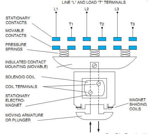
Fgr. 1 Three-pole, solenoid-operated magnetic switch contactor.
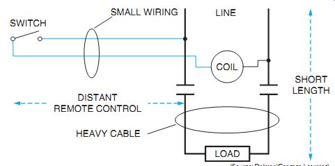
Fgr. 2 An advantage of a remote control load.
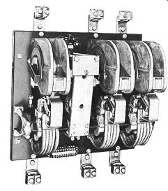
Fgr. 3 Open magnetic contactor "clapper" action size 6.
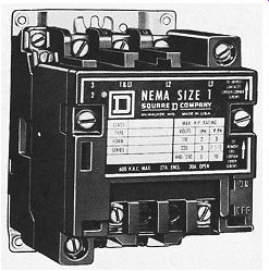
Fgr. 4 Contactor, size 1. Contacts are accessible by removing the two front
screws.
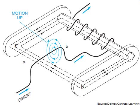
Fgr. 5 Illustration of the magnetic blowout principle. Straight conductor
simulates arc.
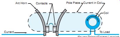
Fgr. 6 Section of blowout magnet with straight conductor replaced by a set
of contacts. An arc is conducting between the contacts.
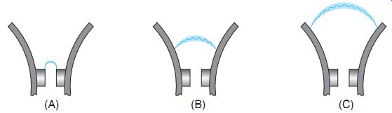
Fgr. 7 Arc deflection between contacts.
Magnetic Blowout
The contactors shown in Fgr. 3 and Fgr. 4 operate on alternating current.
Heavy-duty contact arc-chutes are provided on most of these larger contactors, Fgr. 3. The chutes contain heavy copper coils called blowout coils mounted above the contacts in series with the load to provide better arc suppression. These magnetic blowout coils help to extinguish an electric arc at contacts opening under AC and DC loads. These arcs may be similar in intensity to the electric arc welding process. An arc quenching device is used to ensure longer contact life. Because the hot arc is transferred from the contact tips very rapidly, the contacts remain cool and so last longer.
Contactor and motor starter contacts that frequently break heavy currents are subject to a destructive burning effect if the arc isn't quickly extinguished. The arc that's formed when the contacts open can be lengthened and extinguished by motor action if it's in a magnetic field. This magnetic field is provided by the magnetic blowout coil. Because the coil of the magnet is usually in series with the line, the field strength and extinguishing action are in proportion to the size of the arc.
Fgr. 5 is a sketch of a blowout magnet with a straight conductor (ab) located in the field and in series with the magnet. This figure can represent either DC polarity or instantaneous AC. With AC current, the blowout coil magnetic field and the conductor (arc) magnetic field will reverse simultaneously. According to Fleming's left-hand rule, motor action will tend to force the conductor in an upward direction.
The application of the right-hand rule for a single conductor shows that the magnetic field around the conductor aids the main field on the bottom and opposes it on the top, thus producing an upward force on the conductor.
Fgr. 6 shows a section of Fgr. 5 with the wire (ab) replaced by a set of contacts.
The contacts have started to open and there is an arc between them.
Fgr. 7 shows what happens because of the magnetic action. Part (A) shows the beginning defection of the arc because of the effect of the motor action. Part (B) shows that the contacts are separated more than in Part (A) and the arc is beginning to climb up the horns because of the motor action and the effect of increased temperature. Part (C) of Fgr. 7 shows the arc near the tips of the horns. At this point, the arc is so lengthened that it will be extinguished.
The function of the blowout magnet is to move the arc upward at the same time that the contacts are opening. As a result, the arc is lengthened at a faster rate than will normally occur because of the opening of the contacts alone. It is evident that the shorter the time the arc is allowed to exist, the less damage it will do to the contacts. Most arc-quenching action is based upon this principle.
AC MECHANICALLY HELD CONTACTORS AND RELAYS
A mechanically held relay, or contactor, is operated by electromagnets, but the electromagnets are automatically disconnected by contacts within the relay. Accordingly, these relays are mechanically held in position and no current flows through the operating coils of these electromagnets after switching. It is apparent, there fore, that near continuous operation of multiple units of substantial size will lower the electrical energy requirements. Also, the magnetically held relay, in comparison, will change contact position on loss of voltage to the electromagnet, whereas the mechanically held relay will respond only to the action of the control device.
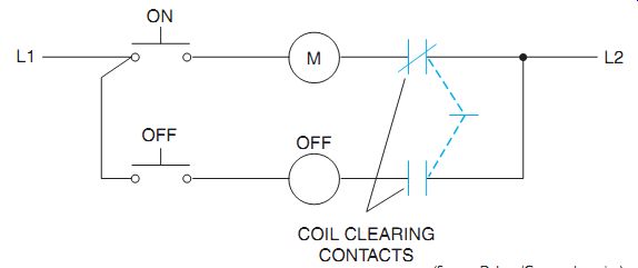
Fgr. 8 Mechanically held contactor control circuit.
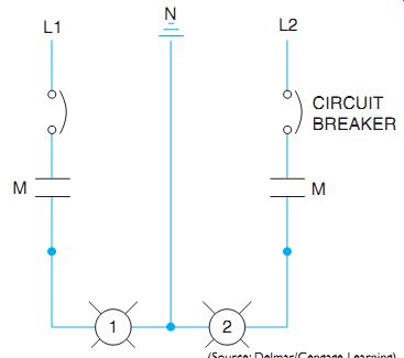
Fgr. 9 Load connections for a 115/230-volt, three-wire lighting load.
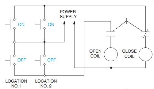
Fgr. 10 Control circuit for a mechanically held lighting contactor controlled
from two locations.
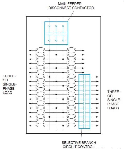
Fgr. 11 Mechanically held contactor loads for three-phase power.
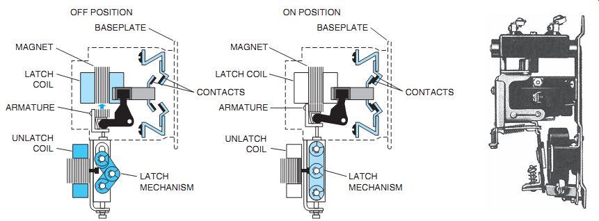
Fgr. 12 Two types of latched-in or mechanically held contactors in service.
The upper coil is energized momentarily to close contacts, and the lower coil
is energized momentarily to open the contact circuit. The momentary energizing
of the coil is an energy-saving feature.
Sequence of Operation
Referring to Fgr. 8, when the "on" push button is pressed momentarily, current flows from L1 through the on push-button contact energizing the M coil through the now closed clearing contact to L2. The relay now closes and latches mechanically. At the same time it closes M contacts (in Fgr. 9), lighting a bank of lamps when the circuit breaker is closed. To unlatch the relay, thereby turning the lamps off, the off button is pressed momentarily, unlatching the relay and opening contacts M, turning off the lamps. Most operating coils are not designed for continuous duty. Therefore, they are disconnected automatically by contacts to prevent an accidental coil burnout. These coil clearing contacts change position alternately with a change in contactor latching position.
Fgr. 10 shows a control circuit with two locations: for controlling a latching contactor and for industrial lighting. All multiple control stations are connected parallel as shown.
Fgr. 11 shows a three-phase power load application using one main contactor to disconnect the distribution panel. Selective single- or three-phase, branch circuits may be switched independently by other mechanically held contactors or relays.
These mechanically held contactors and relays are electromechanical devices, Fgr. 12.
They provide a safe and convenient means of switching circuits where quiet operation, energy efficiency, and continuity of circuit connection are requirements of the installation. E.g., circuit continuity during power failures is often important in automatic processing equipment, where a sequence of operations must continue from the point of interruption after power is resumed-rather than return to the beginning of the sequence. Quiet operation of contactors and relays is required in many control systems used in hospitals, schools, and office buildings. Mechanically held contactors and relays are generally used in locations where the slight hum, characteristic of AC magnetic devices, is objectionable. In addition, mechanically held relays are often used in machine tool control circuits.
These relays can be latched and unlatched through the operation of limit switches, timing relays, starter interlocks, time clocks, photo electric cells, other control relays, or push buttons. Generally, mechanically held relays are available in 10- and 15-ampere sizes; mechanically held contactors are also available in sizes ranging from 30 amperes up to 1200 amperes.
Industrial rated magnetic contactors built to International Electrotechnical Control (IEC), as well as U.S. standards, are generally acceptable throughout the world.
QUIZ:
1. Why are contactors described as both control pilot devices and large magnetic switches controlled by pilot devices?
2. What is the principal difference between a contactor and a motor starter?
3. What causes the arc to move upward in a blowout magnet?
4. Why is it desirable to extinguish the arc as quickly as possible?
5. What will happen if the terminals of the blowout coil are reversed?
6. Why will the blowout coil also operate on AC?
7. What does IEC stand for?
8. "ON" control stations used in multiple locations are connected in series or parallel, for latched-in contactors?