AMAZON multi-meters discounts AMAZON oscilloscope discounts
LEARNING GOALS:
- • Tell how relays differ from motor starters.
- • List the principal uses of each magnetic relay.
- • Identify single- and double-throw contacts; single- and double-break contacts.
- • Draw the wiring diagram symbols for relays.
- • Describe the operation and use of mechanically held relays.
- • Draw elementary diagrams of control and load for mechanically held relays.
- • Connect wiring for mechanically held relays.
- • Identify dusttight, plug-in, and solid-state relays.
- • Identify and connect a thermostat relay.
CONTROL RELAYS
Control magnetic relays are used as auxiliary devices to switch control circuits and large motor starter and contactor coils, and to control small loads such as small motors, solenoids, electric heaters, pilot lights, audible signal devices, and other relays, Fgr. 1 and Fgr. 2.
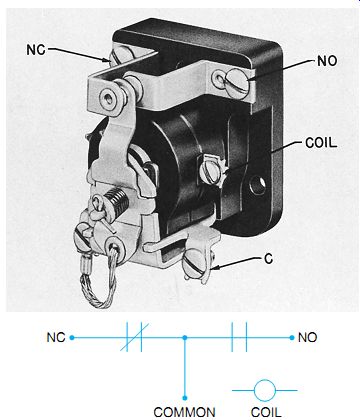
Fgr. 1 Single-pole, double-throw, single-break AC general-purpose control
relay with wiring symbols.
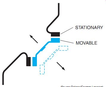
Fgr. 2 Double-break contacts.
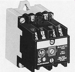
Fgr. 3 Four-pole control relay with four normally open contacts. To change
from the normally open to the normally closed reversing contact, invert 180° and rein stall the cartridges.
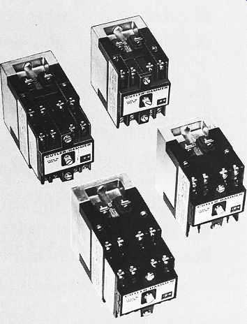
Fgr. 4 Multiple relays.
A magnetically held relay is operated by an electromagnet, which opens or closes electrical contacts when the electromagnet is energized.
The position of the contacts changes by spring and gravity action when the electromagnet is de-energized.
Relays are generally used to enlarge or amplify the contact capability, or multiply the switching functions of a pilot device by adding more contacts to the circuit, Fgr. 3 and Fgr. 4.
Most relays are used in control circuits; there fore, their lower ratings (0-15 amperes maximum to 600 volts) show the reduced current levels at which they operate.
Magnetic relays don't provide motor over load protection. This type of relay is ordinarily used in a two-wire control system (any electrical contact-making device with two wires). When ever it's desired to use momentary contact pilot devices, such as push buttons, any available normally open contact can be wired as a holding circuit in a three-wire system (see Unit 5 and Glossary). The contact arrangement and a description of the magnetic structure of relays were presented in Unit 3, as motor starters.
Starters, contactors, and relays are similar in construction and operation but are not identical.
Control relays are available in single- or double-throw arrangements with various combinations of normally open and normally closed contact circuits. Although there are some single-break contacts used in industrial relays, most of the relays used in machine tool control have double-break contacts. The comparison can be seen in Fgr. 1 and Fgr. 2. Looking at the relay contacts in Fgr. 2, note the upper contact being open at two points, making it a double break. One set of normally closed and one set of normally open contacts can be seen with the wiring symbols in Fgr. 1. This is also a double-throw contact because it has a common connection between the normally open and normally closed contacts, such as can be seen in Fgr. 1.The common terminal between the normally closed and normally open contacts make this a "single-pole, double-throw" relay.
It may be of particular interest to an electrician to know about changing contacts that are normally open to normally closed, or the other way around, normally closed to normally open.
Most machine tool relays have some means to make this change. It ranges from a simple flip over contact to removing the contacts and relocating with spring location changes.
Also, by overlapping contacts in this case, one contact can be arranged to operate at a different time relative to another contact on the same relay. E.g., the normally open contact closes (makes) before the normally closed con tact opens (breaks).
Relays differ in voltage ratings, number of contacts, contact rearrangement, physical size, and in attachments to provide accessory functions such as mechanical latching and timing.
(These are discussed later.)
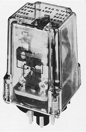
Fgr. 5 Dust-proof, transparent enclosed control relay.
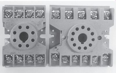
Fgr. 6 Eight- and eleven-pin tube sockets.
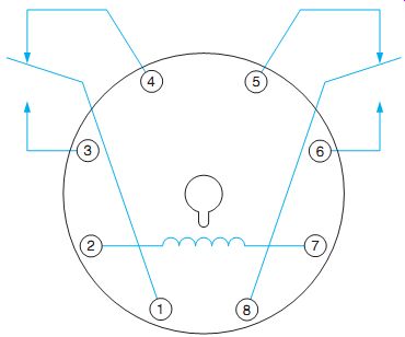
Fgr. 7 Connection diagram of an eight-pin control relay.
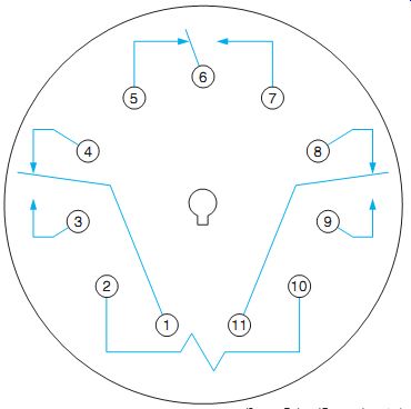
Fgr. 8 Connection diagram of an eleven-pin control relay.
In using a relay for a particular application, one of the first steps should be to determine the control (coil) voltage at which the relay will operate. The necessary contact rating must be made, as well as the number of contacts and other characteristics needed. Because of the variety of styles of relays available, it's possible to select the correct relay for almost any application.
Relays are used more often to open and close control circuits than to operate power circuits.
Typical applications include the control of motor starter and contactor coils, the switching of solenoids, and the control of other relays. A relay is a small but vital switching component of many complex control systems. Low-voltage relay systems are used extensively in switching residential and commercial lighting circuits and individual lighting fixtures.
Although control relays from various manufacturers differ in appearance and construction, they are interchangeable in control wiring systems if their specifications are matched to the requirements of the system.
Control relays are available in many shapes and configurations. Fgr. 5 shows a dust proof, transparent enclosure of a general purpose eight-pin control relay. These relays are available in both eight- and eleven-pin models. They plug into eight- and eleven-pin tube sockets, Fgr. 6. These relays are reliable, inexpensive, and can be replaced quickly without having to rewire the circuit. Eight-pin relays generally contain two sets of double-acting contacts. A connection diagram of an eight-pin relay is shown in Fgr. 7.Eleven-pin relays contain three sets of double-acting contacts. A connection diagram for an eleven-pin relay is shown in Fgr. 8.
Another type of control relay contains small reed contacts that are enclosed in glass. A coil causes these contacts to open or close magnetically.
Consulting various industrial motor control catalogs, one will find many different voltages and current values. Basically, the following values are generally found:
Industrial Control Relays
NEMA:
contact voltage ratings-300 V and 600 V
contact ampere ratings-most 10 amps, some 20 amps
IEC (International Electrotechnical Control):
- contact voltage rating-600 V
- contact ampere rating--most 10 amps, some 15 amps
GENERAL-PURPOSE RELAYS:
- contact voltage rating-600 V
- contact ampere rating--most 10 amps, some to 30 amps
GENERAL PURPOSE-PLUG-IN RELAYS:
- contact voltage rating-277 V
- contact ampere rating--10 amps per pole not to exceed 20 amps per relay
SOLID-STATE RELAY
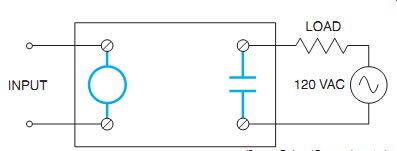
Fgr. 9 The load side and control side are separated from each other.
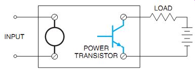
Fgr. 10 A power transistor is used to connect a DC load to the line.
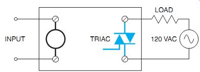
Fgr. 11 A solid-state relay intended to connect an AC load to the line uses
a triac.
Solid-state relays have several advantages over relays with mechanical contacts. Solid state relays have no moving parts, are resistant to shock and vibration, and are sealed against dirt and moisture. The greatest advantage of the solid-state relay is the fact that the input or control voltage is isolated from the line voltage.
This prevents voltage spikes and electrical noise from being transmitted into the control section of the circuit, Fgr. 9.
Solid-state relays can be used to control DC or AC loads. The relay illustrated in Fgr. 9 shows a set of normally open contacts being used to connect the load to the power line. In reality, this set of contacts is actually a solid-state device.
If the relay is intended to control a DC load, a power transistor is used to connect the load to the line, Fgr. 10. The transistor is a semi conductor device that has the ability to control the flow of direct current. Although the transistor has the ability to regulate the flow of current in much the same way a water valve can control the flow of water, in this application the transistor is used as a switch. When it's off, it's completely off. When it's on, it's turned completely on.
Solid-state relays intended to control the operation of AC loads use an electronic device called a triac to connect the load to the line, Fgr. 11. The triac is a bidirectional device that will permit current to flow through in either direction. It has the ability to control alternating current in much the same way that a transistor controls direct current. Like the transistor, the triac is used as a solid-state switch in this circuit.
Solid-state relays generally apply 3 to 32 volts DC to the input to control the operation of the relay. Two basic methods are employed. The first method uses a reed relay. The coil of the relay is connected to the input voltage. The magnetic field produced by the direct current closes a reed contact and connects the base of the power transistor to the line or the gate of the triac to the line, Fgr. 12.
The second method involves the use of a light-emitting diode (LED) and photo-sensitive components. This method is generally referred to as optoisolation. The input voltage operates an LED, Fgr. 13. The output device is a phototransistor or phototriac. When the LED turns on, it has the effect of connecting the base of the transistor to the line or the gate of the triac to the line. Opto-isolation is the most widely used method because it prevents voltage spikes and electrical noise from being transmit ted from the load side of the circuit to the control side. These types of solid-state relays are commonly used in the output section of programmable controllers.
Solid-state relays can be obtained in a variety of case styles and sizes. Some are housed in four pin in-line IC circuit cases and are intended to control other solid-state devices. Others may be housed in cases intended to be heat-sinked and are capable of controlling several amperes. The solid-state relay shown in Fgr. 14 is rated to control a 10-ampere load at 240 volts. This relay should be mounted on a heat sink.
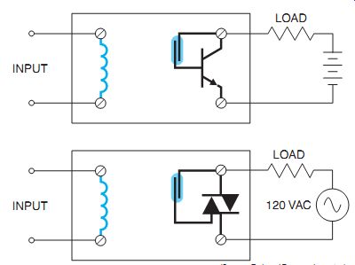
Fgr. 12 Reed relay used to control the output device.
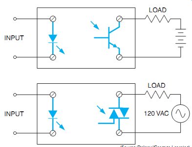
Fgr. 13 Optoisolation uses a light-emitting diode (LED) to control a phototransistor
or phototriac.
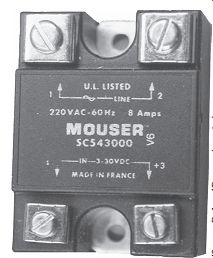
Fgr. 14 Solid-state relay.
SURGE PROTECTION
The coils of magnetic devices such as relays often generate large voltage spikes and electrical noise when they are switched on or off. As a general rule, magnetic relays are not affected by the electric noise and the voltage spikes induced in the system, but electronic devices are.
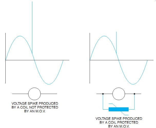
Because electronic control is becoming more and more prevalent in industry, it's often necessary to eliminate as much electrical noise and transient voltages as possible. One method of eliminating noise and voltage spikes is to use a transient suppressor, Fgr. 15. The transient suppressor connects directly across the coil of the relay as shown in Fgr. 16.
The transient suppressor is a solid-state de vice called a metal oxide varistor (M.O.V.). The M.O.V. is basically a voltage-sensitive resistor.
As long as the voltage remains below a certain point, the M.O.V. exhibits a very high resistance in the range of several hundred thousand ohms. However, when the voltage reaches a certain point, the M.O.V. suddenly drops to a very low value of resistance, acting almost like a short circuit. This change in resistance occurs rapidly, generally in the range of 3 to 5 nanoseconds, preventing the voltage spike from going any higher, Fgr. 17. The energy in the spike is dissipated as heat by the M.O.V. The M.O.V. will have a voltage rating slightly higher than the circuit voltage. A 120-volt coil would typically have an M.O.V. with a voltage rating of about 140 volts connected across it.
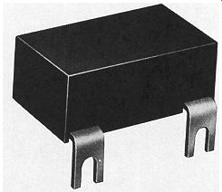
Fgr. 15 Transient suppressor.
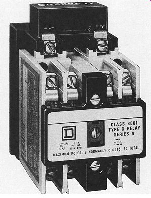
Fgr. 16 Transient suppressor installed on a magnetic relay.
Fgr. 17 The M.O.V. prevents the voltage spike from rising above a certain
point.
THERMOSTAT RELAY
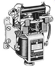
Thermostat-type relays, Fgr. 18, are used with three-wire, gauge-type thermostat controls or other pilot controls having a slowly moving element, which makes a contact for both the closed and open positions of the relay.
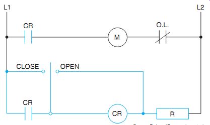
The contacts of a thermostat control device usually cannot handle the current to a starter coil; therefore, a thermostat relay must be used between the thermostat control and the starter, Fgr. 19.
When the moving element of the thermostat control touches the closed contact, the relay closes and is held in this position by a maintaining contact. When the moving element touches the open contact, the current flow by passes the operating coil through a small resistor and causes the relay to open. The resistor is usually built into the relay and serves to prevent a short circuit.
Fgr. 18 Thermostat relay.
Fgr. 19 Starter coil (M) is controlled by thermostat relay.
The thermostat contacts must not overlap or be adjusted too closely to one another as this may result in the resistance unit being burned out. It is also advisable to compare the inrush current of the relay with the current rating of the thermostat.
QUIZ:
1. What are control relays?
2. What are typical uses for control relays?
3. What are the advantages of a mechanically held relay?
4. Why are mechanically held relays energy-saving devices?
5. Why does the coil (CR) in Fgr. 19 drop out when the thermostat touches the open position?
6. Match each item in the alphabetical column with the appropriate item in the numbered columns.
a. Double-break contact
b. Industrial control relay
c. Single pole, double throw
d. Normally closed contact
e. Single-break contact
f. Relay coil
g. Normally open contact
7. What device is used to connect the load to the line in a solid-state relay intended to control a DC load?
8. What device is used to connect the load to the line in a solid-state relay intended to control an AC load?
9. What is opto-isolation?
10. What type of device is used to suppress voltage spikes in relay circuits?