AMAZON multi-meters discounts AMAZON oscilloscope discounts
Goals:
- Describe the difference between closed and open push buttons.
- Draw the wiring diagram symbols for push buttons and pilot lights.
- Draw simple circuits using normally open and closed push buttons.
- Connect combination push buttons in simple circuits.
- Explain single- and double-break contacts.
- List the types of control operators on control stations.
- Draw simple circuits using a selector switch.
- Wire simple circuits with a selector switch.
PUSH BUTTONS
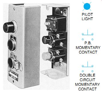
A push-button station is a device that provides control of a motor through a motor starter by pressing a button that opens or closes contacts. It is possible to control a motor from as many places as there are stations-through the same magnetic controller. This can be done by using more than one push-button station. A single-circuit push-button station is shown in Fgr. 1.
Two sets of momentary contacts are usually provided with push buttons so that when the button is pressed, one set of contacts is opened and the other set is closed. The use of this combi nation push button is simply illustrated in the wiring diagram of Fgr. 2. When the push button is in its normal position as shown in Fgr. 2(A), current flows from L1 through the normally closed contacts, through the red pilot light (on top) to L2 to form a complete circuit; this lights the lamp. Because the power push-button circuit's open by the normally open contact, the green pilot lamp does not glow. Note that this situation is reversed when the button is pushed, as shown in Fgr. 2(B). Current now flows from L1 through the pushed closed contact and lights the green pilot lamp when completing the circuit to L2. The red lamp is now out of the circuit and does not glow. However, because the push buttons are momentary contact (spring loaded), we re turn to the position shown in Fgr. 2(A) when pressure on the button is released. Thus, by connecting to the proper set of contacts, either a normally open or a normally closed situation is obtained. Normally open and normally closed mean that the contacts are in a rest position, held there by spring tension, and are not subject to either mechanical or electrical external forces. (See the Glossary for more detailed definitions.) Push-button stations are made for two types of service: standard-duty stations for normal applications safely passing coil currents of motor starters up to size 4, and heavy-duty stations when the push buttons are to be used frequently and subjected to hard or rough usage. Heavy-duty push-button stations have higher contact ratings.
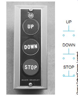
Fgr. 1 Push-button control station with a general purpose enclosure. The
enclosure is usually made of molded plastic or sheet metal. This station contains
three push buttons; two are normally open and one is normally closed.
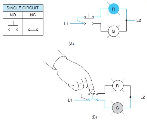
Fgr. 2 Combination push button. (A) Red pilot light is lit through normally
closed push-button contact; (B) green pilot light is lit when the momentary
contact button is pushed.
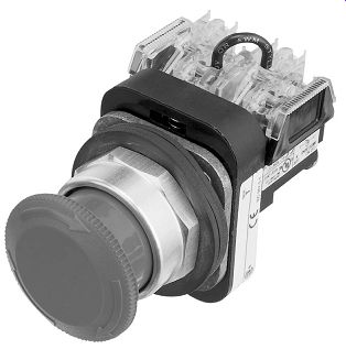
Fgr. 3 Open push-button unit with mushroom head.
The push-button station enclosure containing the contacts is usually made of molded plastic or sheet metal. Some double-break contacts are made of copper. However, in most push buttons, silver-to-silver contact surfaces are provided for better electrical conductivity and longer life.
Fgr. 3 shows a combination, normally open and normally closed, push-button unit with a mushroom head for fast and easy access such as may be required in a safety circuit. This is also called a palm-operated push button, especially when it's used as a safety device for both opera tor and machine, such as a punch press or emergency stop in a control station. The push-button terminals in Fgr. 2 represent one-half of the terminals shown in Fgr. 3 and Fgr. 4, for a double-pole, double-throw push button.
Because control push buttons are subject to high momentary voltages caused by the inductive effect of the coils to which they are connected good clearance between the contacts and insulation to ground and operator is provided.
The push-button station may be mounted adjacent to the controller or at a distance from it.
The amount of current broken by a push button is usually small. As a result, operation of the controller is hardly affected by the length of the wires leading from the controller to a remote push-button station.
Push buttons can be used to control any or all of the many operating conditions of a motor, such as start, stop, forward, reverse, fast, and slow. Push buttons also may be used as remote stop buttons with manual controllers equipped with potential trip or low-voltage protection.
SELECTOR SWITCHES
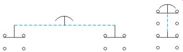
Selector switches, as can be seen in Fgr. 5, are usually "maintained" contact position, with three and sometimes two selector positions. Se lector switch positions are made by turning the operator knob-not pushing it. Fgr. 5(A) is a single-break contact arrangement, and Fgr. 5(B) is a double-break contact, disconnecting the control circuit at two points. These switches may also have a spring return to give momentary contact operation.
Fgr. 6(A) shows a single-break contact selector switch connected to two lights. The red light may be selected to glow by turning the switch to the red position, Fgr. 6(B). Current now flows from line 1 through the selected red position of the switch, through the red lamp to line 2, completing the circuit. Note this switch has an off position in the center. There are two position selector switches available with no off position. Here, whichever light is selected would burn continuously.
Fgr. 4 Terminal configurations used by different manufacturers of Fgr. 3
push button. Both configurations represent the same push button.
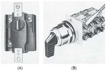
Fgr. 5 Open selector switches.
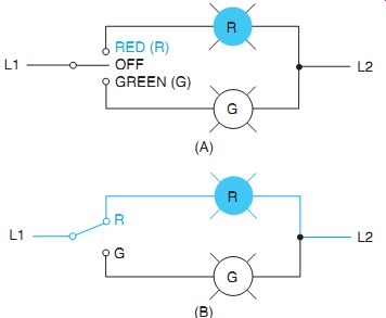
Fgr. 6 Elementary diagram using (A) a single-break, three-position selector
switch and (B) two-position, single-break switch.
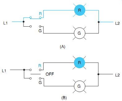
Fgr. 7 Heavy-duty, double-break selector switch for (A) two-position and (B) three-position switches.
Fgr. 7(A) is an elementary diagram of the heavy-duty, double-break selector switch similarly shown in Fgr. 5. Note that the red light will glow, as shown in Part (A), with the two-position switch in this position, the green indicating lamp is de-energized, there is no "off " position. Fgr. 7(B) illustrates a three-position selector switch containing an "off " position. Both lamps may be turned off using this switch, but not in Part (A).
Fgr. 8 Push-button control station with pilot light and associated wiring
symbols for components.
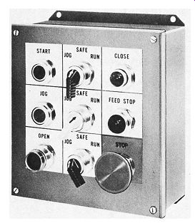
Fgr. 9 Control station with push buttons, selector switches, and indicating
lights.
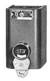
Fgr. 10 Mechanical lockout-on-stop push button.
CONTROL STATIONS
A control station may contain push buttons alone, Fgr. 8, or a combination of push buttons, selector switches, and pilot lights (indicating lights), Fgr. 9. Indicating lights may be mounted in the enclosure. These lights are usually red or green and are used for communication and safety purposes. Other common colors available are amber, blue, white, and clear. They indicate when the line is energized, the motor is running, or any other condition is designated.
Control stations may also include switches that are key, coin, or hand-operated wobble sticks. A wobble stick is a stem-operated push button for operation from any direction. There are ball lever push-button operators for a gloved hand or for frequent operations.
Nameplates are installed to designate each control operation. These can be seen in Fgr. 1 and Fgr. 8. These control operators are commonly used in control circuits of magnetic devices in factory production machinery.
Combination indicating light, nameplate, and push-button units are available. These illuminated push buttons and indicating lights are designed to save space in a wide variety of applications such as control and instrument panels, laboratory instruments, and computers.
Miniature buttons are also used for this purpose.
Standard control station enclosures are available for normal general-purpose conditions, whereas special enclosures are used in situations requiring watertight, dust-tight, oil-tight, explosion-proof, or submersible protection. Provisions are often made for padlocking stop buttons in the open position (for safety purposes), Fgr. 10. Relays, contactors, and starters cannot be energized while an electrician is working on them with the stop button in this position.
QUIZ:
1. What is meant by normally open contacts and normally closed contacts?
2. Why is it that normally open and normally closed contacts cannot be closed simultaneously?
3. How are colored pilot lights indicated in wiring diagrams? Select the best answer for each of the following.
4. A single-break control is a:
a. heavy-duty selector switch
b. single-circuit push button
c. standard-duty selector switch
d. double-circuit push button
5. Control stations may contain
a. push buttons
b. selector switches
c. indicating lights
d. all of these
6. A wobble stick is
a. operated from any direction
b. knob controlled
c. palm controlled
d. glove operated
7. Common selector switches are
a. one position
b. two positions
c. three positions
d. two and three positions
8. Most push buttons are
a. momentary contact
b. single contact
c. double contact
d. a combination
9. Control station enclosures are
a. general purpose
b. explosion proof
c. watertight
d. all of these
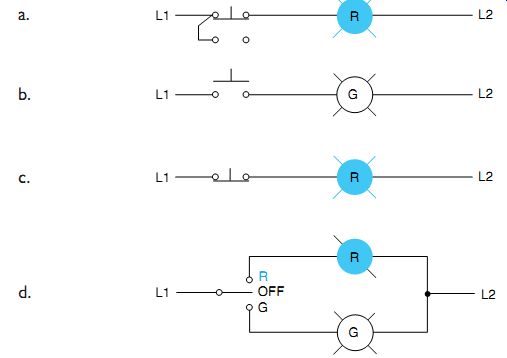
10. The diagram that illustrates a single-circuit, normally closed push button is: