AMAZON multi-meters discounts AMAZON oscilloscope discounts
GOALS:
- • Identify the primary types of timing relays.
- • Explain the basic steps in the operation of the common timing relays.
- • List the factors that affect the selection of a timing relay for a particular use.
- • List applications of several types of timing relays.
- • Draw simple circuit diagrams using timing relays.
- • Identify on- and off-delay timing wiring symbols.
INTRODUCTION
A timing relay is similar to a control relay, except that certain of its contacts are designed to operate at a preset time interval, or time lag, after the unit's energized, or de-energized.
Many industrial control applications require timing relays that can provide dependable ser vice and are easily adjustable over the timing ranges. The proper selection of timing relays for a particular application can be made after a study of the service requirements and with a knowledge of the operating characteristics inherent in each available device. A number of timing devices are manufactured with features suitable for a wide variety of applications.
-------------------
APPLICATION
Timing relays are used for many applications. A few examples are:
- to control the acceleration of contactors of motor starters
- to time the closing or opening of valves on refrigeration equipment
- for any application where the operating sequence requires a delay
PNEUMATIC TIMERS
The construction and performance features of the pneumatic (air) timer make it suitable for the majority of industrial applications. Pneumatic timers have the following characteristics:
- unaffected by normal variations in ambient temperature or atmospheric pressure
- adjustable over a wide range of timing periods
- good repeat accuracy
- available with a variety of contact and timing arrangements
- This type of relay has a pneumatic time-delay unit that's mechanically operated by a magnet structure. The time-delay function depends on the transfer of air through a restricted orifice by the use of a reinforced synthetic rubber bellows or diaphragm. The timing range is adjusted by positioning a needle valve to vary the amount of orifice or vent restriction.
The process of energizing or de-energizing pneumatic timing relays can be controlled by pilot devices such as push buttons, limit switches, or thermostatic relays. Because the power drawn by a timing relay coil is small, sensitive control devices may be used to control the operating sequence.
Pneumatic timing relays are used for motor acceleration and in automatic control circuits.
Automatic control is necessary in applications where repetitive accuracy is required, such as controls for machine tools and control of sequence operations, industrial process operation, and conveyor lines.
Fgr. 1 Pneumatic timer attachment.
Fgr. 2 Bellows-type timing unit.
Pneumatic timers provide time delay through two arrangements. The first, on delay, means that the relay provides time delay when it's energized; the second arrangement, off delay, means the relay is de-energized when it provides time delay. Fgr. 1 is a typical pneumatic timer attachment. It is an "add-on" attachment for a type of relay. The lower screw is the timing adjustment that allows the limited passage of air to escape. The timer here has a flat rubber diaphragm. Fgr. 2 shows a rubber bellows type of timing action.
The speed with which the bellows rises is set by the position of the needle valve at the bottom. The setting of the needle valve determines the time interval that must elapse between the solenoid closing and the rise of the bellows to operate the switch. If the needle valve is almost closed, an appreciable length of time is required for air to pass the valve and cause the bellows to rise.
When the solenoid is de-energized, the plunger drops by force of gravity and by the action of the reset spring. The downward movement of the plunger forces down, thus resetting the timer almost instantaneously.
Both types of pneumatic timing controls do the same thing, that's , to control the timing period, or cycle, of the timing period to open or close contacts.
TIMED CONTACTS
Tbl 1 illustrates standard diagram symbols for timed contacts. These symbols are used by manufacturers and others in wiring diagrams. The first symbol, from left to right, represents a normally open contact (when the relay is de-energized). When the relay is energized, there is a time delay in closing (on delay). Thus, it's a normally open, timed closing (NOTC) contact. Similarly, the second symbol is for a normally closed contact. After the relay coil is energized, there is a time delay before this contact opens (NCTO). The third symbol is for a normally open contact, at rest. When the relay coil is energized, this contact closes instantly. It will stay closed as long as the coil is energized. When the coil is de-energized, there is a time delay before the contact opens (NOTO). This mode is called off delay. The last symbol represents a normally closed timing contact. When the timer is energized, this contact opens rapidly and remains open. When current to the coil is disconnected, there is a time delay before the contact closes to its normal position.
INSTANTANEOUS CONTACTS
Most pneumatic timers may have non-timed contacts in addition to timing contacts. These non-timed contacts are controlled directly by the timer coil, as in a general-purpose control relay.
These auxiliary contacts are often used on pneumatic timers to combine the functions of a standard or conventional control relay and a timing relay. The regular, or instantaneous contacts, are easily installed, or added, to the timer on the job site.
MOTOR-DRIVEN TIMERS

Tbl 1 Standard Elementary Diagram Symbols for Timed Contacts
--
Min. Time Delay: 0.05 second Max. Time Delay: 3 minutes Minimum Reset Time: .075 second Accuracy: ±10 percent of setting Contact Ratings:
AC 6.0 A, 115 V 3.0 A, 230 V 1.5 A, 460 V 1.2 A, 550 V
DC 1.0 A, 115 V
0.25 A, 230 V
Operating Coils: Coils can be supplied for voltages and frequencies up to 600 volts, 60 hertz AC and 250 volts DC.
Types of Contacts: One normally open and one
--
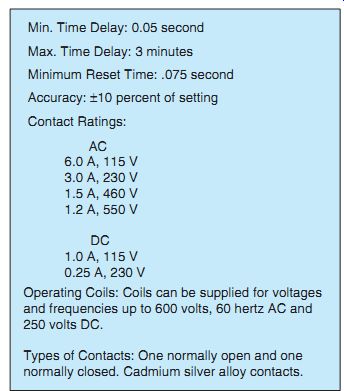
Fgr. 3 (above) Typical specifications.
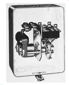
Fgr. 4 Motor-driven process timer in a general-purpose enclosure.
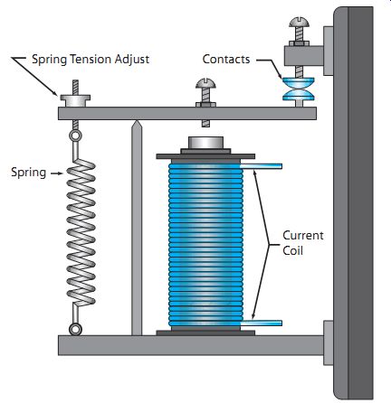
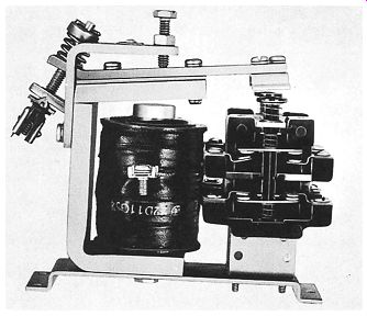
Fgr. 5 (A) Series type relay; (B) DC series relay.
When a process has a definite on and off operation, or a sequence of successive operations, a motor-driven timer is generally used, Fgr. 3 and Fgr. 4. A typical application of a motor driven timer is to control laundry washers where the loaded motor is run for a given period in one direction, reversed, and then run in the opposite direction. Motor-driven timers are also used where infrequent starting of large motors is required.
Generally, this type of timer consists of a small, synchronous motor driving a cam-dial assembly on a common shaft. A motor-driven timer successively closes and opens switch contacts, which are wired in circuits to energize control relays or contactors to achieve desired operations.
DC SERIES RELAY
Generally, the name of a relay is descriptive of its major purpose, construction, or principle of operation. A common application of DC series relays is to time the acceleration of DC motors.
E.g., the coil of the DC series relay, Fgrs 5(A) and 5(B), is connected in series with the starting resistance so that the starting cur rent of the motor passes through it.
The contacts of the series relay are connected to an auxiliary circuit.
The relay contacts shown in Fgr. 5(A) are usually connected to control the coils of a magnetic contactor. The armature is light and constructed so that it's very fast in operation.
As the starting current passes through the coil, the armature is pulled down (overcoming the resistance of a spring), causing small contacts to open. When the current in the coil has decreased to a predetermined value, the spring pulls the armature back and the contacts close.
The value of current at which the coil loses control of the armature is determined by the spring setting. Crane control is another common application.
CAPACITOR TIME LIMIT RELAY
Assume that a capacitor is charged by connecting it momentarily across a DC line and then the capacitor DC is discharged through a relay coil. The current induced in the coil will decay slowly, depending on the relative values of capacitance, inductance, and resistance in the discharge circuit.
If a relay coil and a capacitor are connected in parallel to a DC line, Fgr. 6, the capacitor is charged to the value of the line voltage and a current appears in the coil. If the coil and capacitor combination is now removed from the line, the current in the coil will start to decrease along the curve shown in Fgr. 6.
If the relay is adjusted so that the armature is released at current i1, a time delay of t1 is obtained. The time delay can be increased to a value of t2 by adjusting the relay so that the armature won't be released until the current is reduced to a value of i2.
A potentiometer is used as an adjustable resistor to vary the time. This resistance-capacitance (RC) theory is used in industrial electronic and solid-state controls also. This timer is highly accurate and is used in motor acceleration control and in many industrial processes.
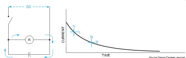
Fgr. 6 Charged capacitor discharging through a relay coil. The graph at the
right illustrates the current decrease in the coil.
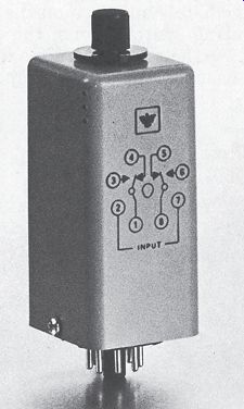
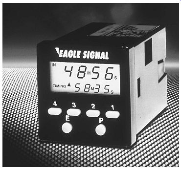
Fgr. 7 On-delay electronic timer designed to plug into an eight-pin tube socket.
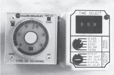
Fgr. 8 Electronic timers that perform multiple functions or are intended for
use as off-delay timers plug into eleven-pin sockets.
ELECTRONIC TIMERS
Electronic timers have become increasingly popular in industrial applications for several reasons. They generally have better repeat accuracy, are less expensive, can be set for a greater range of time delays, and many perform multiple timing functions. Electronic timers use some type of electronic circuit to accomplish a time delay. Some use a basic RC time constant and others contain quartz clocks and integrated circuit timers. Many of these timers can be set for time delays with an accuracy of 0.01 second.
Electronic timers are available in various case styles. Many are designed to plug into eight- or eleven-pin tube sockets. These have the advantage of being easy to replace in the event they fail. Timers intended for use only as on-delay timers are generally designed to plug into an eight-pin socket, Fgr. 7. Timers that can be set for multiple functions or as off delay timers generally plug into eleven-pin tube sockets, Fgr. 8.
Although electronic timers may be similar in function, they may connect differently. Different manufacturers stipulate different connection methods. Always refer to the manufacturer's specifications before trying to connect a timer into a circuit. The connection diagrams for two different eleven-pin timers are shown in Fgr. 9. Another type of electronic timer is shown in Fgr. 10. This timer has the case style of a standard control relay.
It is sometimes necessary to connect electronic timers into the circuits in a different manner than other types of timers. Mechanical timers, such as pneumatic timers, depend on power being applied to or removed from the coil to initiate the action of the timer. In the circuit shown in Fgr. 11, the action of the timer starts when switch S1 is closed. After a delay of 5 seconds the lamp will turn on. The lamp in Fgr. 12 will turn on immediately when switch S1 is closed. It will remain on for a period of 5 seconds when switch S1 is opened.
The timers in Fgr. 11 and Fgr. 12 are pneumatic timers; their time-delay mechanism is accomplished by air refilling a bellows or diaphragm.
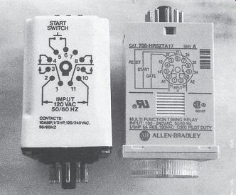
Fgr. 9 Connection diagram for two eleven-pin timers.
Fgr. 10 Solid-state timing relay.
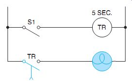
Fgr. 11 The lamp will turn on after a delay of 5 seconds.
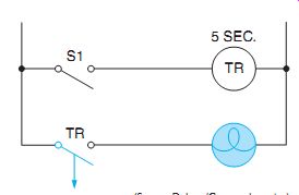
Fgr. 12 The lamp will turn on immediately when switch S1 closes. The lamp
will remain on for 5 seconds when switch S1 opens.
Fgr. 13 Connection diagram for an eleven-pin timer.
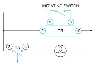
Fgr. 14 The action of the timer starts when pins 5 and 6 are shorted by the
initiating switch.
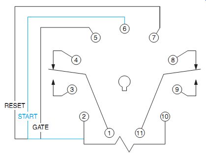
Fgr. 15 Connection diagram for an Allen Bradley eleven-pin timer.
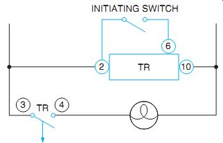
Fgr. 16 The action of the timer starts when the initiating switch connects
pins 2 and 6.
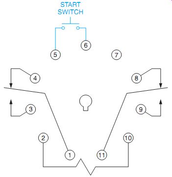
Electronic timers must have power connected to them in order to provide a time delay. Electronic on-delay timers are not problematic because their time delay starts when power is applied. Off-delay timers, however, must have power applied at all times to permit the timing circuit to operate. These timers use a separate contact to initiate the action of the timer.
Fgr. 13 illustrates the connection diagram for one of the timers shown in Fgr. 8. The diagram shows a normally open push button labeled START SWITCH connected between pins 5 and 6.This indicates that when the timer is used as an off-delay timer, the action of the timer is initiated by shorting pins 5 and 6. A simple circuit for connecting this timer is shown in Fgr. 14.Notice that pins 2 and 10 are connected directly to the power line. When the initiating switch closes, contact TR will close immediately and turn on the lamp. When the initiating switch opens, the timer starts counting. At the end of the time delay, contact TR reopens and turns off the lamp.
The connection diagram for an Allen Bradley eleven-pin timer is shown in Fgr. 15.
Although this timer is similar to the Dayton timer, the action of the timer is started by connecting pins 2 and 6 together. A schematic diagram for connecting this timer is shown in Fgr. 16.
SELECTING A TIMING RELAY
In selecting a timing relay for a specific application, the following factors should be carefully considered:
- + Length of time delay required
- + Timing range required
- + Allowable error
- + Cycle of operation and reset time
- + Cost
- + Additional requirements
Solid-state timers, like relays, are very reliable provided their cycle of operation isn't exceeded. Overworking is harmful in that it creates internal heat, destroying the unit.
Length of Time Delay Required
The length of time delay required is determined by the type of machine or process that the timer will control. This time delay will range from a fraction of a second to as long as several minutes.
Timing Range Required
The phrase "timing range" means the various time intervals over which the timer can be adjusted. Timers are available that can be set for a time delay of 1 second, 100 seconds, or any value of delay between 1 and 100 seconds.
When selecting a timer for use with a machine or process, the range should be wide enough to handle the various time-delay periods that may be required by the machine or process.
The exact timing value for any position within the timing range must be found by trial and error. A scale provided with a timer is intended primarily to permit a quick reset of the timer to the timing position previously determined to be correct for a given operation.
Allowable Error
All timers are subject to some error; that's , there may be a plus or minus time variation between successive timing operations for the same setting. The amount of error varies with the type of timer and the operating conditions.
The error is usually stated as some percentage of the time setting.
The percentage of error for any timer depends on the type of timer, the ambient temperature (especially low temperatures), coil temperature, line voltage, and the length of time between operations.
Cycle of Operation Required and Reset Time
For one type of timer, the timer becomes operative when an electrical circuit opens or closes.
A time delay then occurs before the application process begins. As soon as the particular process action is complete, the timer circuit resets itself. The circuit must be energized or de-energized each time the timing action is desired.
A second type of timer is called a process timer. When connected into a circuit, this timer provides control for a sequence of events, one after another. The cycle is repeated continuously until the circuit's de-energized.
An important consideration in the selection of a timer is the speed at which the timer resets.
Reset time is the time required for the relay mechanism to return to its original position.
Some industrial processes require that the relay reset instantaneously. Other processes require a slow reset time. The reset time varies with the type of timing relay and the length of the time delay.
Cost
When there are several timers that meet the requirements of a given application, it's advisable to select the timer with the smallest number of operating parts. In other words, select the simplest timer. In most cases, this timer will probably be the lowest in cost.
Additional Requirements
Several additional factors must be considered in selecting electromagnetic and solid state timers:
- + Type of power supply.
- + Contact ratings.
- + Timer contacts--a choice of normally open or normally closed contacts can usually be made.
- + Temperature range--the accuracy of some timers varies with the temperature; how ever, temperatures below freezing may affect the timer accuracy.
- + Dimensions--the amount of space available may have a bearing on the selection of a timer.
QUIZ:
1. List several applications for a motor-driven timer.
2. Which timer is the most commonly used in industrial applications?
3. How is the pneumatic timer adjusted?
4. List six factors to be considered when selecting a timing relay for a particular use.
5. List several additional factors that will affect the selection of a timing relay.
6. On a separate sheet of paper, draw an elementary diagram of a fractional horsepower, manual motor starter. When the starter contact is closed, it will energize a pneumatic timing relay coil through the overload heater. After the timer coil is energized, the circuit will show a delayed closing contact that energizes a small motor on 120 volts.
7. Connect these components in Fgr. 17:
a. The start push button on the timer coil
b. Load 1 to NOTC
c. Load 2 to NCTO
d. Show proper symbols
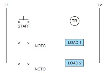
Fgr. 17
8. Connect the following components in Fgr. 18:
a. Start push button to the timer coil
b. Load 1 to NCTC
c. Load 2 to NOTO
d. Show proper symbols
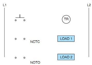
Fgr. 18