AMAZON multi-meters discounts AMAZON oscilloscope discounts
GOALS:
- Explain the use of limit switches in the automatic operation of machines and machine tools.
- Wire a simple two-wire circuit using a limit switch.
- Read and draw normally open (NO) and normally closed (NC) wiring symbols in a simple circuit.
- Explain the use and operation of solid-state proximity switches.
LIMIT SWITCHES
The automatic operation of machinery requires the use of switches that can be activated by the motion of the machinery. The limit switch, ill. 1, is used to convert this mechanical motion into an electrical signal to switch circuits.
The repeat accuracy of the switches must be reliable and the response virtually instantaneous.
The size, operating force, stroke, and manner of mounting are all critical factors in the installation of limit switches due to mechanical limitations in the machinery. The electrical ratings of the switches must be carefully matched to the loads to be controlled.
The limit switch contacts shouldn't be over loaded. Contacts must be selected according to the proper load, that's , the proper current and voltage, according to the manufacturer's specifications. ill. 2 shows the switch used to its capacity, and how it's used to control a load above its capacity by controlling a contactor to switch a heavier load.
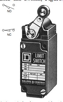
ill. 1 Limit switch shown with wiring symbols.
In general, the operation of a limit switch begins when the moving machine or moving part of a machine strikes an operating lever, which actuates the switch, ill. 1. The limit switch, in turn, affects the electrical circuit controlling the machine and its movement.
Limit switches are used as pilot devices in the control circuits of magnetic starters to start, stop, speed up, slow down, or reverse electric motors. Limit switches may be used either as control devices for regular operation or as emergency switches to prevent the improper functioning of machinery. They may be momentary contact (spring return) or maintained contact types. Most limit switches, as shown in ill. 1, have normally open and normally closed contacts that are mechanically connected, or interlocked.
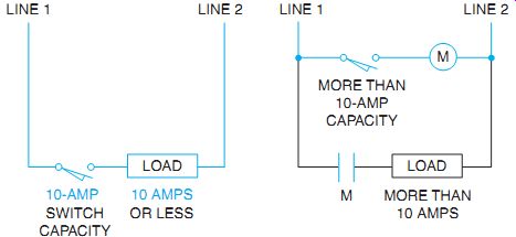
ill. 2 Proper use of limit switches.
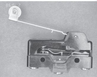
ill. 3 Spring-loaded contact of a micro-limit switch.
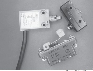
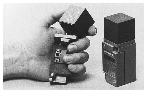
ill. 4 Microswitches in different case styles.
MICRO-LIMIT SWITCHES
Another type of limit switch often used in different types of control circuits is the micro-limit switch or microswitch. Microswitches are much smaller in size than the limit switch shown in ill. 1. This permits them to be used in small spaces that wouldn't be accessible to the larger device. Another characteristic of the microswitch is that the actuating plunger requires only a small amount of travel to cause the contacts to change position. Most microswitches require a movement of approximately 0.015 inch or 0.38 mm to change the contact position. Switching the contacts with this small amount of movement is accomplished by spring loading the contacts as shown in ill. 2.A small amount of movement against the spring will cause the movable contact to snap from one position to another, ill. 3.
Electrical ratings for the contacts of the basic microswitch are generally in the range of 250 volts AC and 10 to 15 amperes, depending on the type of switch. The basic microswitch can be obtained in different case styles and with different operating levers and mechanisms, ill. 4.
SOLID-STATE PROXIMITY SWITCHES
Solid-state proximity switches use various methods to sense objects. They can be switched by a nearby or passing object. No physical con tact is necessary to operate a proximity switch as it's with a limit switch. These self-contained, two-wire devices are available in normally open or normally closed switching positions, both AC and DC. ill. 5 shows a simple, normally open proximity switch in a circuit. The switch can be connected in series or parallel. ill. 6 shows normally open and normally closed switch wiring for DC, four-wire operation.
Manufacturers color code or adequately mark their terminals for wiring. Always keep the manufacturer's installation instructions for future reference.
Capacitive Proximity Sensor (Switches)
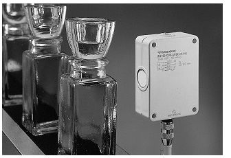
Capacitive proximity sensors are designed to detect both metallic and nonmetallic targets.
They are ideally suited for liquid level control (such as float switch control) and for sensing powdered or granulated materials. For best operation, they should be used in an environment with relatively constant temperature and humidity. ill. 7 features glass-reinforced plastic housing capacitive sensors. Different shapes and mountings are available.
Inductive Proximity Sensors
Description: Compact inductive proximity sensors are also complete, self-contained switches.
They are designed to detect the presence of all metals without making contact. Some models are quite elaborate and include LEDs to indicate "power on," "switch start," a "shorted condition," and when a "target is present." ill. 8 shows an inductive proximity sensor.
The head of the sensor can be rotated in the field to any one of five sensing positions: top, or any one of four side positions, ill. 9.
Pancake-type (low-profile) solid-state sensors are designed to detect targets at distances up to 100 mm (4.0 in.). The sensors can be used for applications where the distance between the sensor and target varies greatly or where long distance sensing is required. The sensors are two-wire devices that can be corrected in the same manner as a mechanical limit switch, ill. 10.
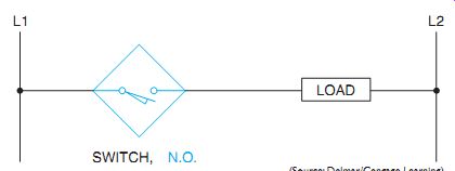
ill. 5 Elementary diagram showing two-wire construction (AC or DC).
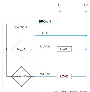
ill. 6 Typical four-wire construction for DC, normally open and normally
closed.
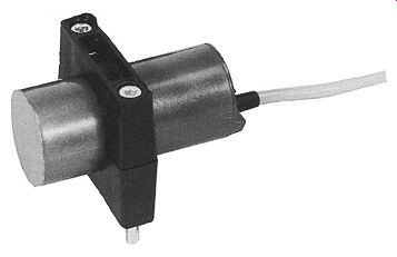
ill. 7 Capacitive proximity sensor with a glass reinforced plastic housing.
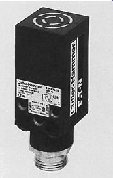
ill. 8 Compact inductive proximity sensor with pin base connector.
ill. 9 Proximity sensor with rotating sensor head.
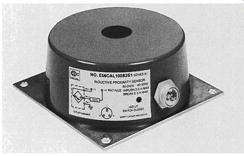
ill. 10 Low-profile, pancake-type inductive proximity sensor.
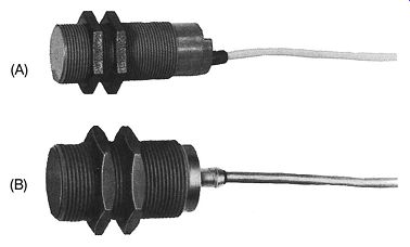
ill. 11 Solid-state cylindrical proximity sensor.
A solid-state cylindrical-shaped proximity switch can be used in small or hard-to-reach places. This type of switch can be wired in series or parallel, ill. 11.
The sensing head is mounted where the object is to be sensed. It is then wired to a chassis (amplifier/power supply). The chassis usually contains the electronic circuitry and a screw driver slot for a sensitivity adjustment.
Operation. Inductive proximity switches operate on the eddy current principle. When a metal object moves into the electromagnetic field of the sensing head, eddy currents are induced in the object. This causes a change in the loading of the oscillator (electronics producing the field), which then operates the output device.
Application. Proximity switches are typically used on production assembly lines in the following ways: to detect metal objects through non metal barriers, where metal objects must be differentiated from nonmetal objects; where touching of the objects must be avoided, as with freshly painted or highly polished parts; as void and jam detectors; for counting; in special and extreme environments; and in many other types of applications.
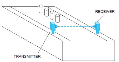
ill. 12 Photodetector with separate transmitter and receiver.
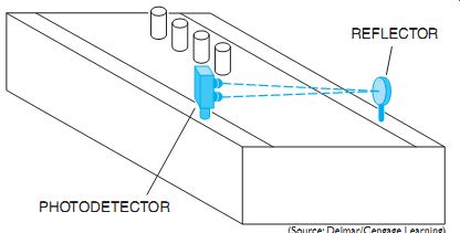
ill. 13 Photodetector contains both the transmitter and receiver.
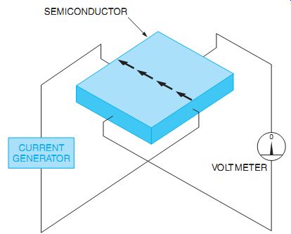
ill. 14 The Hall generator is constructed by passing a constant current through
a semiconductor.
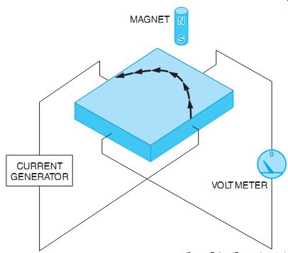
ill. 15 A magnetic field causes the current path to bend.
Photodetectors
Photodetectors are very popular throughout the industry because of their reliability and flexibility. Photodetectors basically consist of a light source and a light detector. The light source is generally a long-life incandescent lamp or LED and the light detector can be a photodiode or a photoconductive device called a cad cell. Photodiodes are used if high-speed operation is an important factor. Photodetectors used in burglar alarm systems commonly use infrared LEDs as the light source because it's invisible to the human eye.
Some photodetectors use a separate transmitter and receiver, ill. 12. In this example, the photodetector is used to count cans on a conveyor line. Each time a can breaks the light beam a counter counts up once. Other types of photodetectors house both the transmitter and receiver in the same case. This type of unit uses a reflector, ill. 13. Because both the transmitter and receiver are mounted at the same position, the advantage of this unit's that control wiring is connected at only one location.
This permits the reflector to be mounted in places where it would be difficult to run control wires. Some reflector units have a range of 20 feet or more.
Hall Effect Sensors
Hall effect sensors have become increasingly popular for many applications. Hall effect sensors detect the presence of a magnetic field but don't work on the principle of induction. Hall generators operate by passing a constant cur rent through a piece of semiconductor material, ill. 14. A zero center voltmeter is connected across the opposite sides of the semiconductor. As long as the current flows through the center of the semiconductor, there is no voltage drop across it. However, if a magnet is brought near the semiconductor the current path will defect to one side, producing a voltage across the semiconductor, ill. 15. As long as the magnetic field is present, a voltage will be produced across the semiconductor.
Hall effect sensors are fast acting and are often used to measure the speed of rotating objects, ill. 16. In this example, a mag net with salient (projecting) poles is mounted on a motor shaft. The Hall sensor can deter mine the speed of the motor by measuring the number of pulses per second.
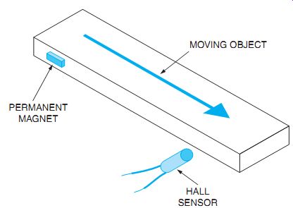
Another use for the Hall sensor in industrial applications is the bumperless limit switch, ill. 17. In this example, a piece of moving equipment has a permanent magnet attached to it. A Hall sensor is held stationary at the position where a limit switch is needed. When the magnet moves in line with the sensor, it has the same effect as hitting the arm of a limit switch.
Because the magnet does not make physical contact with the sensor, however, there is no wear on the sensor and no mechanical arm to break or get out of adjustment.
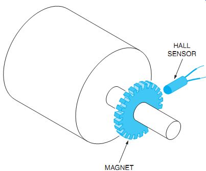
ill. 16 Hall effect sensor used to measure motor speed.
ill. 17 Hall effect sensor used as a bumperless limit switch.
ill. 18 Ultrasonic detectors operate by emitting high-frequency sound waves.
ill. 19 Ultrasonic detectors can be used to position objects.
ill. 20 Ultrasonic proximity detector
Ultrasonic Proximity Detectors
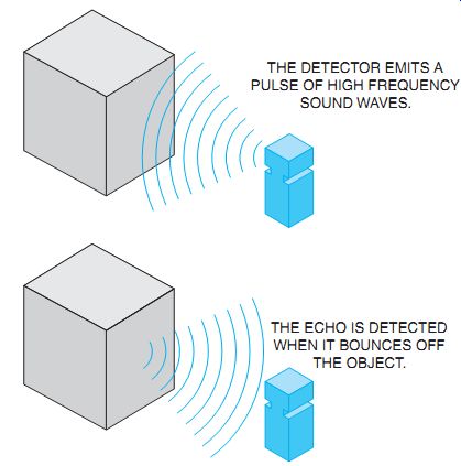
Another type of proximity detector is the ultra sonic detector. This detector emits a high frequency sound wave and then detects the echo when it bounces off the object, ill. 18.
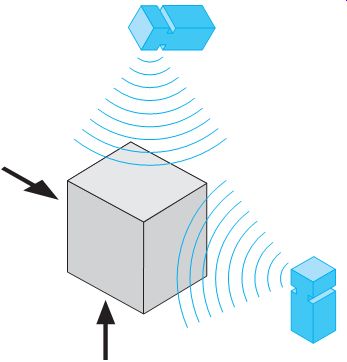
Ultrasonic detectors can accurately calculate the distance to an object by measuring the time delay between pulse emission and pulse return. For this reason ultrasonic detectors are often used to position objects, ill. 19. An ultrasonic proximity detector is shown in ill. 20.
QUIZ:
1. Draw a simple circuit showing how a red pilot light is energized when a limit switch is operated by a moving object.
2. On what principle does an inductive proximity sensing unit work?
3. What is the advantage of a photodiode in a photodetector?
4. What type of photodetector is often used in burglar alarm systems? Why?
5. What do Hall effect sensors detect?
6. Hall effect sensors don't depend on electromagnetic induction to operate. Explain how they can sense the presence of a magnetic field if induction isn't involved.
7. How do ultrasonic proximity detectors operate?
8. Explain how an ultrasonic detector can measure the distance to an object.
9. What is the average amount of movement necessary to cause the contacts of a micro-limit switch to change position?
10. How is it possible for the miscroswitch to change contact position with such a small amount of movement of the activating arm?