AMAZON multi-meters discounts AMAZON oscilloscope discounts
Goals:
- Describe the purpose and functions of flow switches.
- Connect a flow switch to other electrical devices.
- Draw and read wiring diagrams of systems using flow switches.
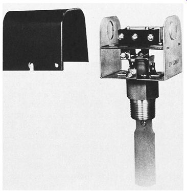
ill. 1 Flow switch
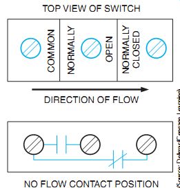
ill. 2 Typical electrical terminals and contact arrangement of a flow switch.
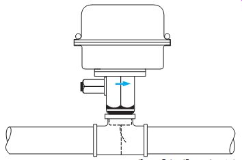
ill. 3 Fluid flow switch installed.
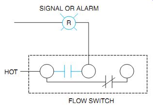
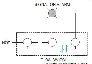
ill. 4 Flow switch used to sound alarm or light signal when flow occurs
using normally open contacts.
ill. 5 Flow switch used to sound alarm or light signal when there is no
flow using normally closed contacts.
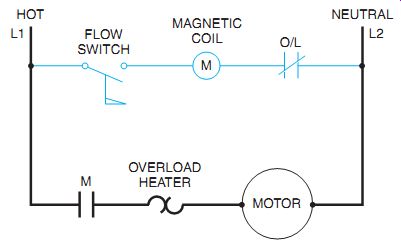
ill. 6 Flow switch used with single-phase circuit starts the motor when flow
occurs and stops the motor when there is no flow.
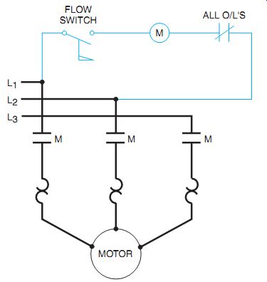
ill. 7 Flow switch used with three-phase circuit starts the motor when flow
occurs and stops the motor when there is no flow.
A flow switch is a device that can be inserted in a pipe so that when liquid or air flows against a part of the device called a paddle, a switch is activated (ill. 1). This switch either closes or opens a set of electrical contacts. The contacts may be connected to energize motor starter coils, relays, or indicating lights. In general, a flow switch contains both normally open and normally closed electrical contacts, ill. 2.
ill. 3 shows a flow switch installed in a pipeline tee. Half couplings are welded into larger pipes for flow switch installations.
Typical applications of flow switches are shown in ill. 4 through ill. 8. These applications are commonly found in the chemical and petroleum industries. Vaporproof electrical connections must be used with vaporproof switches.
The insulation of the wire leading to the switches must be adequate to withstand the high temperature of the liquid inside the pipe. (Consult the NEC© for insulation temperature ratings.) The elementary diagram in ill. 6 shows the electrical connections for a flow switch. When the flow switch contact closes with sufficient fluid or air movement, the M coil is energized. This closes larger contact M in the motor circuit, starting the motor. Airflow or sail switches are also used in ducts in air conditioning systems. An M coil could be a contactor to close and energize electric heating elements in an air duct heating system, ill. 8. These heating elements are designed to operate at their rating with a sufficient movement of air.
Without adequate airflow, the heating elements may burn out. The flow switch prevents this by detecting the airflow before energizing the heater and stopping it with a flow loss. The action is similar in cooling systems. Iced-over refrigeration coils would restrict airflow. The flow switch is used to detect insufficient air movement over the refrigeration coils, stopping the refrigeration compressor and starting a defrost cycle. Although the construction of air-flow switches differs from that of liquid flow switches, the electrical connections are similar.
An airflow switch is shown in ill. 9.
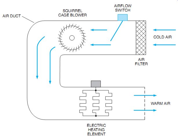
ill. 8 An air duct heating system, flow switch controlled.
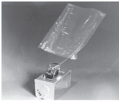
ill. 9 Airflow switch.
QUIZ:
1. What are typical uses of flow switches?
2. Draw a line diagram to show that a green light will glow when liquid flow occurs.
3. Draw a one-line diagram showing a bell that will ring in the absence of flow. Include a switch to turn off the bell manually.