AMAZON multi-meters discounts AMAZON oscilloscope discounts
GOALS:
• Demonstrate safe working habits.
• Prepare motors for startup.
• Start up newly installed motors.
• Troubleshoot motors using basic sense faculties.
• Separate circuit operation into logical steps for troubleshooting.
• Use industrial control index for troubleshooting tips.
• Seat new motor brushes, AC and DC.
• Test a solid-state diode.
• Change solid-state control modules according to the direction of a visual control panel.
WARNING
High voltage and rotating parts may cause serious or fatal injuries. Installation, operation, and maintenance of electrical machinery should be performed by qualified people! All maintenance and repairs should be made with good, deliberate safety practices in mind.
Fundamental to any job approach is a good safety procedure. Remember, SAFETY FIRST, THE JOB IS SECOND!
MOTOR STARTUP
After new motors and controls are installed, they should be checked for operation under load for an initial period of at least one hour. During this time, the electrician can observe if any unusual noise or hot spots develop. The operating current must be checked against the name plate ampere rating. This requires skill in the proper connection, setting, and reading of an ammeter. The preferred ammeter is the type that has the clamp around the wire.
The nameplate ampere reading times the service factor (if any) sets the limits of the steady cur rent; this value should not be exceeded.
If the motor has not been installed in a clean, well-ventilated place, clean the area. Good housekeeping, as well as direct accident and fire prevention techniques, must be emphasized at all times.
MOTOR MOUNTS
Motor mounts must be checked to be sure that they are secure and on a firm foundation. If necessary, add grout to secure the mounts. Ball-bearing motors can be mounted on sidewalls or the ceiling, vertically or horizontally.
Rotate the end shields to place grease fit tings, plugs, or any openings in the best, or most accessible, location. Oil or grease the bearings if necessary.
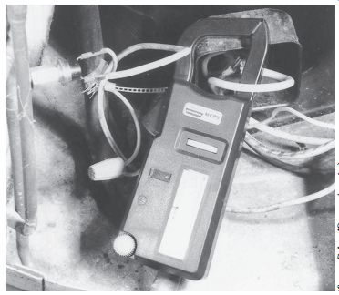
Ill. 1 Using an ammeter around a wire.
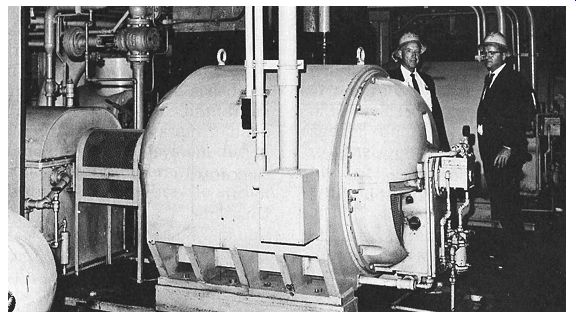
Ill. 2 A motor on a firm, secure foundation.
NAMEPLATE
Check the power supply against the name plate values; they should agree. Most motors will operate successfully with the line voltage within 10 percent (plus or minus) of the name plate value; or within 5 percent of the frequency (hertz). Most 220-volt motors can be used on 208-volt network systems but with slightly modified performance. Generally 230-volt motors should not be used on 208-volt systems.
To reconnect a dual-voltage motor to a desired voltage, follow the instructions on the connection diagram on the nameplate. (See also "Interpretation and Application of Simple Wiring and Elementary Diagrams.") Motor starter overload relay heaters must be installed with the proper size. The motor won’t run without them. Sizing information is found inside the control enclosure cover. The starting fuses should be checked in a similar manner. The selection of the correct fuse size must be in accordance with the NEC or with local requirements.
Collector Rings and Commutators
The collector rings on wound rotor motors are sometimes coated with a film at the factory to protect them while in stock and during shipment. The brushes may be fastened in a raised position. Before putting the motor into service, the collector ring surface must be cleaned of the protective coating. The brushes then must be set down on the collector ring or commutator.
When the motor is in service, keep the rings clean and maintain their polished surfaces.
Chocolate brown is a good operating color for commutators. Ordinarily, the rings will require only occasional wiping with a piece of canvas or non-linting cloth. Don’t let dust, dirt, moisture, or oil accumulate between the collector rings.
Brushes
Brushes should move freely in the holders. At the same time, they must make firm, even con tact with the collector rings and commutators.
When installing new brushes, fit them carefully to the collector rings. Be sure that the pigtail conductors are securely fastened to, and make good contact with, the brush holders. It may be necessary to "sand in" brushes to fit the contour of commutator or slip rings.
LOADS
Electrical
A close check on operating line voltages, both at the incoming line and close to the motor terminals, may reveal imbalances that can be corrected. An imbalanced three-phase electrical system can cause trouble. Avoid unbalanced single-phase loading on a three-phase distribution panel. Check for required surge suppressors for solid-state devices.
Mechanical
Operate the motor without a load to check rotation and free running action. The desired direction of rotation is the required direction of rotation of the driven load. Incorrect rotation direction of some gear boxes, machines, and equipment may cause severe damage. To reverse rotation of a three-phase motor, inter change any two line leads. To reverse rotation of a single-phase motor, follow the connection diagram. The connected loads should be well balanced to reduce vibration. A smooth-running machine is much more efficient and will cause less trouble later.
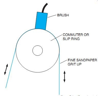
Ill. 3 Fitting a brush in place.
TROUBLESHOOTING BASICS
The first step is to shut down the machine and lock it out for repair or adjustment. The expert troubleshooter has mastered basic circuit concepts. The most valuable troubleshooting asset is the ability to apply common sense when analyzing a control operation. Also, good maintenance personnel learn to use sensory functions to diagnose and locate trouble.
++ LOOKING may reveal contacts stuck and hung up, thereby creating open circuits.
++ LISTENING may indicate loose parts, faulty bearings, excessive speed, and so on.
++ SMELLING may indicate burning insulation or a coil failure.
++ TOUCHING may reveal excessive motor shaft play, vibration, or abnormal heat.
This seemingly oversimplified procedure to locate a problem has saved many hours of labor.
Consider the length of time it would take to become thoroughly familiar with a complicated schematic diagram, compared with locating a few contacts that are stuck-the result of merely LOOKING.
However, finding a problem in an installation is not usually this easy. An orderly, step-by-step approach is required. Circuit operation is separated in logical parts. Circuits and components are then divided into smaller parts to deter mine their functions, relationships to one another, and the effect that they have on each other in the overall control system operation.
Each step leads to the source of the difficulty, finally pinpointing the problem. This procedure may require the use of a voltage tester, ammeter, multimeter, jumper wires, and other tools.
Check the power supply to see if it’s on and if it’s correct. Test all protective devices. If the coil does not energize, a jumper wire can be placed from L1 to 3 of the control circuit. By jumping across the contacts of the limit switch and push buttons, the circuit operation is separated into logical parts. If the starter coil is now energized, the problem may be in the limit switch, or the stop or start push buttons. Smaller circuits and components are now tested by "jumping" around the limit switch, For example. We may then go to the control station, if necessary. By an orderly process of elimination, by testing all possible fault areas, the problem can be located accurately and efficiently.
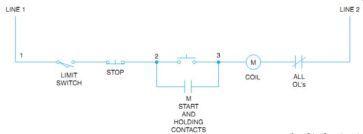
Ill. 4 Control circuit for a troubleshooting exercise.
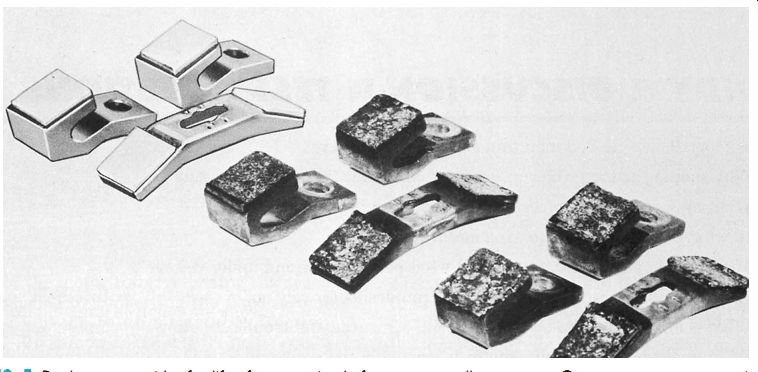
Ill. 5 Replacement guides for life of contact tips. Left: new or excellent
contact. Center: worn contacts, a signal to watch. Right: excessively worn;
change.
Indiscriminate jumping, however, should not be practiced because of the danger of short circuits. For example, a jumper should never be placed across a power-consuming device, such as a contactor coil; voltage or ohmmeter testers are used in this instance. If an ohmmeter is used to test a coil for continuity, the power must be off.
Tbl. 1 and Tbl. 2 are provided as aids to servicing electric control equipment. Use Tbl. 1 as an index. Then refer to Tbl. 2 for signs and solutions. For example, if the problem involves an AC contactor, look under the heading; Contactors, AC operated. In the parenthesis next to it are specific number references (1-12). Refer to Tbl. 2, items 1 through 12 for the signs and solutions to AC operated contactor problems.
Because downtime of a machine may be expensive, the best guideline is to select and replace top quality devices designed for specific applications.
--------------------------
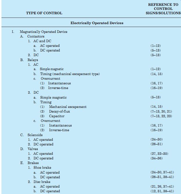
Tbl. 1 Industrial Controls Index to Troubleshooting Suggestions
TYPE OF CONTROL: | REFERENCE TO CONTROL SIGNS/SOLUTIONS:
-- Electrically Operated Devices --
I. Magnetically Operated Device
A. Contactors
1. AC and DC
a. AC operated
b. DC operated
2. DC
B. Relays
1. AC
b. Timing (mechanical escapement type)
c. Overcurrent
(1) Instantaneous
(2) Inverse-time
2. DC
a. Simple magnetic
b. Timing
(1) Mechanical escapement
(2) Decay-of-flux
(3) Capacitor
c. Overcurrent
(1) Instantaneous
(2) Inverse-time
C. Solenoids
1. AC operated
2. DC operated
D. Valves
1. AC operated
2. DC operated
E. Brakes
1. Shoe brake
a. AC operated
b. DC operated
2. Disc brake
a. AC operated
b. DC operated
a. Simple magnetic
II. Motor-Operated Devices
A. Relays
1. Timing
2. Induction disc or cup type
B. Brakes
1. Thrustor operated
C. Thrustors
D. Valves
1. Thrustor operated
2. Geared
E. Rheostats III. Thermally Operated Devices
A. Relays
B. Thermostats
1. Bimetallic
2. Expanding fluid (bulb and bellows) IV. Static Accessories
A. Resistors
B. Rectifiers (dry type)
C. Capacitors
D. Transformers
E. Fuses
----Mechanically Operated Devices---
I. Manually Operated Devices
A. Master switches
B. Drum controllers
C. Push buttons
D. Selector switches
E. Knife switches
F. Manual starters
1. Full voltage (small sizes)
2. Reduced voltage
G. Rheostats
H. Manual contactors II. Otherwise Mechanically Operated Devices
A. Limit switches
B. Speed-sensitive switches
C. Float switches
D. Flow switches
E. Pressure switches
---------
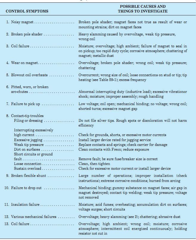
Tbl. 2 Industrial Control Troubleshooting Tips
CONTROL SYMPTOMS | POSSIBLE CAUSES and THINGS TO INVESTIGATE
[CONTROL SYMPTOMS] | [POSSIBLE CAUSES and THINGS TO INVESTIGATE]
[
1. Noisy magnet
2. Broken pole shader
3. Coil failure
4. Wear on magnet
5. Blowout coil overheats
6. Pitted, worn, or broken arc-chutes
7. Failure to pick up
8. Contact-tip troubles
- Filing or dressing
- Interrupting excessively high current
- Excessive jogging
- Weak tip pressure
- Dirt on surfaces
- Short circuits or ground fault
- Loose connection
- Sustain overload
9. Broken flexible shunt
10. Failure to drop out
11. Insulation failure
12. Various mechanical failures
13. Coil failure
14. Sticking
15. Mechanical wear
16. Low trip
17. High trip
18. Fast trip
19. Slow trip
20. Too-short time
21. Too-long time
22. Too-short time
23. Too-long time
24. Noisy magnet
25. Broken pole shader
26. Coil failure
27. Wear on magnet
28. Failure to pick up
29. Failure to drop out
30. Miscellaneous mechanical failures
31. Coil failure
32. Noise
33. Coil failure
34. Failure to open or close
35. Leaks and mechanical failure
36. Coil failure
37. Noisy magnet
38. Excess wear or friction
39. Failure to hold load
40. Failure to set
41. Failure to release
42. Failure to time out
43. Failure to reset
44. Failure to operate properly
45. Short life of thrustor
46. Failure to open or close
47. Wear on segments or shoes
48. Resistor failure
49. Failure to trip (motor burnout)
50. Failure to reset
51. Trips too low
52. Burning and welding of control contacts and shunts
53. Arcing and burning of contacts
54. Bellows distorted
55. Bulb distorted
56. Overheating
57. Corrosion
58. Breakage, distortion and wear
59. Breakdown
60. Breakdown
61. Overheating
62. Insulation failure
63. Premature blowing
64. Too slow blowing
65. Mechanical failures
66. Short contact life
67. Flashover
68. Failure to break arc
69. Failure to make contact
70. Heating
71. Mechanical failure
72. Leaks
]
[ Broken pole shader; magnet faces not true as result of wear or mounting strains; dirt on magnet faces Heavy slamming caused by overvoltage, weak tip pressure, wrong coil Moisture; overvoltage; high ambient; failure of magnet to seal in on pickup; too rapid duty cycle; corrosive atmosphere; chattering of magnet; metallic dust Overvoltage; broken pole shader; wrong coil; weak tip pressure; chattering Overcurrent; wrong size of coil; loose connections on stud or tip; tip heating (see Tbl. 1); excess frequency Abnormal interrupting duty (inductive load); excessive vibration or shock; moisture; improper assembly; rough handling Low voltage; coil open; mechanical binding; no voltage; wrong coil; shorted turns; excessive magnet gap Don’t file silver tips. Rough spots or discoloration won’t harm efficiency Check for grounds, shorts, or excessive motor currents Install larger device rated for jogging service Replace contacts and springs; check carrier for damage Clean contacts with Freon; reduce exposure Remove fault; be sure fuse/breaker size is correct Clean, then tighten Check for excessive motor current or install larger device Large number of operations; improper installation (check instructions); extreme corrosive conditions; burned from arcing Mechanical binding; gummy substance on magnet faces; air gap in magnet destroyed; contact tip welding; weak tip pressure; voltage not removed Moisture; acid fumes; overheating; accumulation dirt on surfaces; voltage surges; short circuits Overvoltage; heavy slamming (see 2); chattering; abrasive dust Overvoltage; high ambient; wrong coil; moisture; corrosive atmosphere; intermittent coil energized continuously; holding resistor not cut in;
Dirt; worn parts; improper adjustment; corrosion; mechanical binding Abrasive dust; improper application (in general not suited for continuous cycling).
Wrong coil; assembled wrong Mechanical binding; wrong or shorted coil; assembled wrong Fluid out or too light; vent too large; high temperature; wrong heaters Fluid too heavy; vent too small; mechanical binding; dirt; low temperature; wrong heaters Dirt in air gap; shim too thick; too much spring and tip pressure; misalignment Shim too thin; weak spring and tip pressure (use brass screws for steel backed shims); gummy substance on magnet faces Same as 20, plus not enough capacitance; not enough resistance Same as 21, plus too much capacitance; too much resistance Same as 1, plus low voltage; mechanical overload; load out of alignment Heavy slamming caused by overvoltage; mechanical underload; wrong coil; low frequency Same as 3, plus mechanical overload (can't pick up); mechanical underload (slam); mechanical failure Overvoltage; underload; broken pole shader; wrong coil; chattering; load out of alignment Same as 7, plus mechanical overload Mechanical binding; gummy substance on magnet faces; air gap in magnet destroyed; voltage not removed; contacts welded Same as 12, plus underload Same as 13, plus mechanical failure of coil Same as 1, plus water hammer Same as 3, plus handling fluid above rated temperature Similar to 28, 29, plus corrosion; scale; dirt; operating above rated pressure
Same as 13, plus handling fluid above rated temperature Same as 2, plus improper adjustment (too much pressure or incorrect lever ratio) Abrasive dust; heavy-duty; high inertia load, excess temperature; scarred wheels Worn parts; out of adjustment; misapplication; failure to use recommended substitute parts Improper adjustment; mechanical binding; coil not de-energized; worn parts Improper adjustment; coil not energized; mechanical binding; low voltage or current; coil open; shorted turns Mechanical binding; worn parts; motor damaged; no voltage motor; dirt Mechanical binding; worn parts; dirt Coils connected wrong; wrong coils; mechanical binding Abrasive dust; dirty oil; water in tank Corrosion; scale; dirt; mechanical binding; damaged motor; no voltage Abrasive dust; very heavy duty; no lubrication (special materials available) Overcurrent; moisture; corrosive atmospheres Heater incorrectly sized; mechanical binding; relay previously damaged by short-circuit current; dirt; corrosion; motor and relay in different ambient temperatures Broken mechanism; corrosion; dirt; worn parts; resetting too soon Wrong heater; relay in high ambient (check temperature of motor) Short circuits on control circuits with too large protecting fuses; severe vibration; dirt; oxidation
Misapplied; should handle very little current and have sealing circuit Mechanical binding; temperature allowed to overshoot Liquid frozen in capillary tube Used above rating; running on starter resistor Excess moisture; salt air; acid fumes Overheating; mechanical abuse; severe vibration; shock High temperature; moisture; overcurrent; overvoltage; corrosive atmosphere; mechanical damage Overload; overvoltage, AC on DC capacitor; moisture; high temperature; mechanical damage; continuous voltage on intermittent types Overload; overvoltage; intermittent-rating device operated too long Overheating; overvoltage; voltage surges; moisture; mechanical damage Extra heating from outside; copper oxide on ferrules and clips (plated ferrules and clips are available); high ambient Wrong-sized fuse for application Abrasive dust and dirt; misapplication; mechanical damage Jogging; handling abnormal currents; lack of lubrication where recommended; abrasive dirt Jogging; short circuits; handling too large motor; moisture; acid fumes; gases; dirt Too much current; too much voltage; (usually DC); misapplication; too much inductance Mechanical damage; dirt; corrosion; wear allowance gone Overcurrent; loose connection; spring clips loose or annealed; oxidation; corrosion Same as 65, plus excessive operating speed Corrosion; mechanical damage; excessive pressure ]
-------------------
HOW TO FIND AN INTERMITTENT FAULT
A loose electrical terminal connection or a control pilot device with an intermittent open circuit can cause a motor to stop running. The intermittent fault is one of the most difficult problems encountered during electrical troubleshooting. It need not be frustrating while troubleshooting, if a simple procedure is followed. First check the "LOOK, SMELL, TOUCH, LISTEN'' sensory method to diagnose a possible malfunction. Think SAFETY FIRST while doing this procedure.
Next, connect a test relay with its normally open contact in series with its coil. Connect two test leads, with alligator clips for convenience, to the wire ends. Connect one wire end to the relay coil and the other wire to the opposite side of the normally open contact. Clip the test relay across the suspected circuit. Close, or energize, the relay manually by pushing the armature closed. Now wait for the problem to occur.
When it does, the test relay will be de-energized.
When the relay is no longer energized, you have found the problem. If a "closed contact" is live on the supply side and dead on the starter coil load side, the problem is in the contact or device located here. While checking the test relay periodically and it’s still energized, move it around in the circuit, as shown, until you locate the "troublemaker."
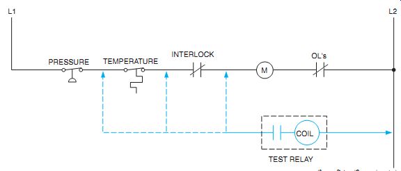
Ill. 6 Finding an intermittent fault.
SOLID-STATE EQUIPMENT
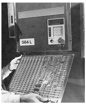
Ill. 7 Troubleshooting complex systems is simplified by modular construction.
This industrial process controller has removable circuit boards to allow for
troubleshooting and also for convenient upgrading of capabilities.
Modular construction makes troubleshooting easier. On large controllers, components can be removed for repair or replacement. Leads disconnect simply by means of plug connectors.
Ill. 7 shows an industrial processor controller, which features the convenient drawout construction of all elements, including circuit boards.
With self-diagnostics on some controllers, each of the circuit boards is checked by the microprocessor. As each board passes the self test routine, this information is displayed on the visual control panel. The panel tells where any problems are located. The malfunctioning modules or circuit boards are then replaced. For electronic equipment, always follow the manufacturer's recommendations about service so as not to void a new equipment guarantee.
With total failures, all fuses should be tested first. If the failure still exists, the power diodes in the converter can be readily tested with an ohmmeter. Remember, these solid-state devices pass current in one direction only. If no continuity is found in either direction on the diode, the diode is open. If continuity exists in both directions, the diode is shorted. In either instance, the diode must be replaced.
QUIZ
1. Who shall operate and maintain electrical machinery?
2. Why should the motor be run for a period of time following checkout?
3. What may occur if a jumper is placed across coil M?
4. In what position do ball-bearing motors function?
5. Motors will operate satisfactorily at what percent over and under voltage?
6. What basic sensory faculties should a troubleshooter rely on?
7. What is an orderly step-by-step procedure in successful troubleshooting?
8. What might be a hazard if a motor is started in the wrong direction?
9. When a coil does not pick up, what are the probable causes?
10. What are the probable causes of a noisy magnet?
11. Why are some solid-state controllers easy to troubleshoot?
12. How is a solid-state diode tested? Explain.
13. Using a portable relay to locate an intermittent fault, how does the relay close?
14. Why must the relay connections be moved around the circuit?