AMAZON multi-meters discounts AMAZON oscilloscope discounts
GOALS:
• Safely check a circuit to determine if power is disconnected.
• Use a voltmeter to troubleshoot a control circuit.
• Use an ohmmeter to test for continuity.
• Use an ammeter to determine if a motor is overloaded.
It’s not a question of if a control circuit will eventually fail, but when it will fail. One of the main jobs of an industrial electrician is to troubleshoot and repair a control circuit when it fails. In order to repair or replace a fault component it’s first necessary to determine which component is at fault. The three main instruments used by an electrician to troubleshoot a circuit are the voltmeter, ohmmeter, and ammeter. The voltmeter and ohmmeter are generally contained in the same meter.
These meters are called multimeters because they can measure several different electrical quantities. Some electricians prefer to use a plunger-type voltage tester because they are not susceptible to ghost voltages. High-impedance voltmeters often give an indication of some amount of voltage, caused by feedback and induction. Plunger-type voltage testers are low impedance devices and require several milliamperes to operate. The disadvantage of plunger-type voltage testers is that they cannot be used to test control systems that operate on low voltage, such as 24-volt systems.
Ammeters are generally the clamp-on type. Both analog and digital meters are in common use. Clamp-on-type ammeters have an advantage in that the circuit does not have to be broken to insert the meter in the line.
SAFETY PRECAUTIONS
It’s often necessary to troubleshoot a circuit with power applied to the circuit. When this is the case, safety should be the first consideration. When de-energizing or energizing a control cabinet or motor control center module, the electrician should be dressed in flame-retardant clothing while wearing safety glasses, a face shield, and a hard hat.
Motor control centers employed through out the industry generally have the ability to release enough energy in an arc-fault situation to kill a person 30 feet away. Another rule that should always be observed when energizing or de-energizing a circuit is to stand to the side of the control cabinet or module. Don’t stand in front of the cabinet door when opening or closing the circuit. A direct short condition can cause the cabinet door to be blown off.
After the cabinet or module door has been opened, the power should be checked with a voltmeter to make certain the power is off. A procedure called check, test, check should be used to make certain that the power is off.
1. Check the voltmeter on a known source of voltage to make certain the meter is operating properly.
2. Test the circuit voltage to make certain that it’s off.
3. Check the voltmeter on a known source of voltage again to make certain that the meter is still working properly.
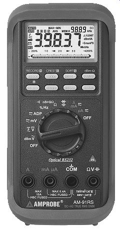
Ill. 1 Digital multimeter.
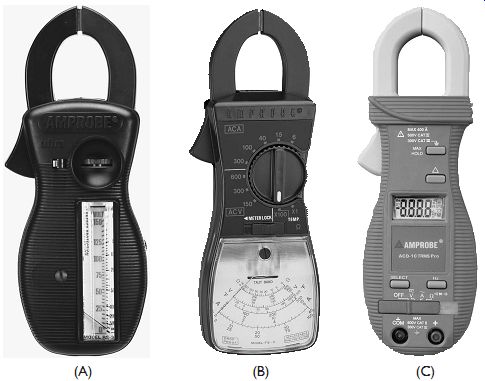
ill. 2 (A) Analog-type clamp-on ammeter with vertical scale. (B) Analog-type
clamp-on ammeter with flat scale. (C) Clamp-on ammeter with digital scale.
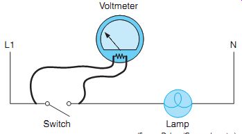
Now assume that the leads of the voltmeter are connected across the lamp.
Question 1: Assuming that the lamp filament is good, would the voltmeter indicate 0 volts, 120 volts, or some value between 0 and 120 volts?
Answer: The voltmeter would indicate 0 volts.
In the circuit shown the switch and lamp are connected in series. One of the basic rules for series circuits is that the voltage drop across all circuit components must equal the applied voltage. The amount of voltage drop across each component is proportional to the resistance of the components and the amount of current flow. Since the switch is open in this example, there is no current flow through the lamp filament and no voltage drop.
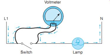
Question 2: If the voltmeter were to be connected across the switch, would it indicate 0 volts, 120 volts, or some value between 0 and 120 volts?
Answer: The voltmeter would indicate 120 volts. Since the switch is an open circuit, the resistance is infinite at this point, which is millions of times greater than the resistance of the lamp filament. Recall that voltage is electrical pressure. The only current flow through this circuit is the current flowing through the volt meter and the lamp filament.
Question 3: If the total or applied voltage in a series circuit must equal the sum of the voltage drops across each component, why is all the voltage drop across the voltmeter resistor and none across the lamp filament?
Answer: There is some voltage drop across the lamp filament because the current of the volt meter is flowing through it. The amount of volt age drop across the filament, however, is so small compared to the voltage drop across the voltmeter, it’s generally considered to be zero.
Assume the lamp filament to have a resistance of 50 ohms. Now assume that the voltmeter is a digital meter and has a resistance of 10,000,000 ohms. The total circuit resistance is 10,000,050 ohms. The total circuit current is 0.000,011,999 ampere (120/10,000,050) or about 12 microamps.
The voltage drop across the lamp filament would be approximately 0.0006 volt or 0.6 milli volt (50 __ 12 _A).
Question 4: Now assume that the lamp filament is open or burned out. Would the voltmeter indicate 0 volts, 120 volts, or some value between 0 and 120 volts?
VOLTMETER BASICS
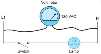
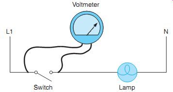
Ill. 3 The voltmeter measures electrical pressure between two points.
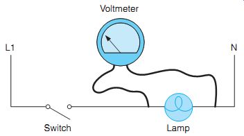
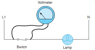
Ill. 4 The voltmeter is connected across the lamp.
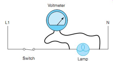
Ill. 5 The voltmeter is connected across the switch.
Ill. 6 A current path exists through the voltmeter and lamp filament.
Recall that one definition of voltage is electrical pressure. The voltmeter indicates the amount of potential between two points in much the same way a pressure gauge indicates the pressure difference between two points. The circuit assumes that a voltage of 120 volts exists between L1 and N. If the leads of a voltmeter were to be connected between L1 and N, the meter would indicate 120 volts.
Now assume that the leads of the voltmeter are connected across the lamp.
Question 1: Assuming that the lamp filament is good, would the voltmeter indicate 0 volts, 120 volts, or some value between 0 and 120 volts? Answer: The voltmeter would indicate 0 volts.
In the circuit shown the switch and lamp are connected in series. One of the basic rules for series circuits is that the voltage drop across all circuit components must equal the applied voltage. The amount of voltage drop across each component is proportional to the resistance of the components and the amount of current flow. Since the switch is open in this example, there is no current flow through the lamp filament and no voltage drop.
Question 2: If the voltmeter were to be connected across the switch as shown, would it indicate 0 volts, 120 volts, or some value between 0 and 120 volts?
Answer: The voltmeter would indicate 120 volts. Since the switch is an open circuit, the resistance is infinite at this point, which is millions of times greater than the resistance of the lamp filament. Recall that voltage is electrical pressure. The only current flow through this circuit is the current flowing through the volt meter and the lamp filament.
Question 3: If the total or applied voltage in a series circuit must equal the sum of the voltage drops across each component, why is all the voltage drop across the voltmeter resistor and none across the lamp filament?
Answer: There is some voltage drop across the lamp filament because the current of the volt meter is flowing through it. The amount of volt age drop across the filament, however, is so small compared to the voltage drop across the voltmeter, it’s generally considered to be zero.
Assume the lamp filament to have a resistance of 50 ohms. Now assume that the voltmeter is a digital meter and has a resistance of 10,000,000 ohms. The total circuit resistance is 10,000,050 ohms. The total circuit current is 0.000,011,999 ampere (120/10,000,050) or about 12 microamps.
The voltage drop across the lamp filament would be approximately 0.0006 volt or 0.6 milli volt (50 __ 12 _A).
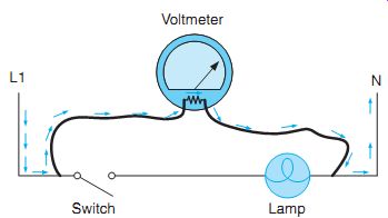
Question 4: Now assume that the lamp filament is open or burned out. Would the voltmeter indicate 0 volts, 120 volts, or some value between 0 and 120 volts?
Answer: The voltmeter would indicate 0 volts. If the lamp filament is open or burned out, a cur rent path for the voltmeter does not exist and the ohmmeter would indicate 0 volts. In order for the voltmeter to indicate voltage it would have to be connected across both components so that a complete circuit would exist from L1 to N.
Question 5: Assume that the lamp filament is not open or burned out and that the switch has been closed or turned on. If the voltmeter is connected across the switch, would it indicate 0 volts, 120 volts, or some value between 0 and 120 volts? Answer: The voltmeter would indicate 0 volts.
Now the switch is closed, the contact resistance is extremely small and the lamp filament now exhibits a much higher resistance than the switch. Practically all the voltage drop will now appear across the lamp, Ill. 10.
Ill. 7 The lamp filament is burned open.
Ill. 8 The voltmeter is connected across both components.
Ill. 9 The switch is turned on or closed.
Ill. 10 Practically all the voltage drop is across the lamp.
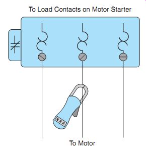
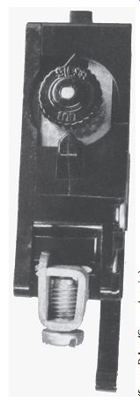
Ill. 11 A clamp-on ammeter is used to check motor current.
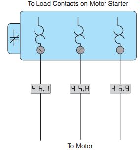
Ill. 12 Ammeter readings indicate that the motor is operating normally.
Ill. 13 Bimetal strip-type overload relays can be set for a higher value
of current.
TEST PROCEDURE EXAMPLE 1
The type of problem determines the procedure to be employed when troubleshooting a circuit. Assume that an overload relay has tripped several times. The first step is to deter mine what conditions could cause this problem.
If the overload relay is a thermal type, a source of heat is the likely cause of the problem. Make mental notes of what could cause the overload relay to become overheated.
1. Excessive motor current.
2. High ambient temperature.
3. Loose connections.
4. Incorrect wire size.
If the motor has been operating without a problem for some period of time, incorrect wire size can probably be eliminated. If it’s a new installation, it would be a factor to consider.
Since overload relays are intended to disconnect the motor from the power line in the event that the current draw becomes excessive, the motor should be checked for excessive current.
The first step is to determine the normal full load current from the nameplate on the motor.
The next step is to determine the percent of full-load current setting for the overload relay.
Example: A motor nameplate indicates the full load current of the motor is 46 amperes. The nameplate also indicates the motor has a ser vice factor of 1.00.The NEC® indicates the over load should be set to trip at 115 percent of the full-load current. The overload heaters should be sized for 52.9 amperes (46 _ 1.15).
The next step is to check the running current of the motor with an ammeter. This is generally accomplished by measuring the motor current at the overload relay. The current in each phase should be measured. If the motor is operating properly, the readings may not be exactly the same, but they should be close to the full-load current value if the motor is operating under load, and relatively close to each other. In the example shown, phase 1 has a current flow of 46.1 amperes, phase 2 has a current flow of 45.8 amperes, and phase 3 has a current flow of 45.9 amperes. These values indicate that the motor is operating normally. Since the ammeter indicates that the motor is operating normally, other sources of heat should be considered. After turning off the power, check all connections to ensure that they are tight. Loose connections can generate a large amount of heat, and loose connections close to the overload relay can cause the relay to trip.
Another consideration should be ambient temperature. If the overload relay is located in an area of high temperature, the excess heat could cause the overload relay to trip prematurely. If this is the case, bimetal strip type over load relays, can often be adjusted for a higher setting to offset the problem of ambient temperature. If the overload relay is the solder melting type, it will be necessary to change the heater size to offset the problem, or install some type of cooling device such as a small fan. If a source of heat cannot be identified as the problem, the overload relay probably has a mechanical defect and should be replaced.
Now assume that the ammeter indicated an excessively high-current reading on all three phases. In the example, phase 1 has a current flow of 58.1 amperes, phase 2 has a current flow of 59.2 amperes, and phase 3 has a current flow of 59.3 amperes. Recall that the full-load nameplate current for this motor is 46 amperes. These values indicate that the motor is overloaded. The motor and load should be checked for some type of mechanical problem such as a bad bearing or possibly a brake that has become engaged.
Now assume that the ammeter indicates one phase with normal current and two phases that have excessively high current. In the example shown, phase 1 has a current flow of 45.8 amperes, phase 2 has a current flow of 73.2 amperes, and phase 3 has a current flow of 74.3 amperes. Two phases with excessively high current indicate that the motor probably has a shorted winding. If two phases have a normal amount of current and one phase is excessively high, it’s a good indication that one of the phases has become grounded to the case of the motor.

Ill. 14 Ammeter readings indicate that the motor is overloaded.
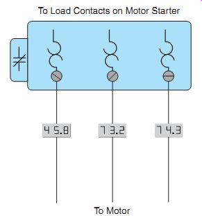
Ill. 15 Ammeter readings indicate that the motor has a shorted winding.
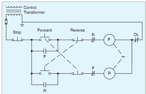
Ill. 16 Reversing starter with interlocks.
Ill. 17 Checking components for continuity with an ohmmeter.
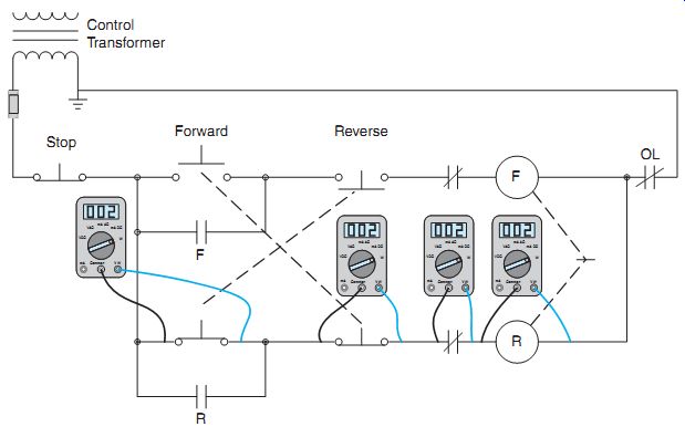
Ill. 18 Testing to determine if voltage is being applied to the coil.
TEST PROCEDURE EXAMPLE 2
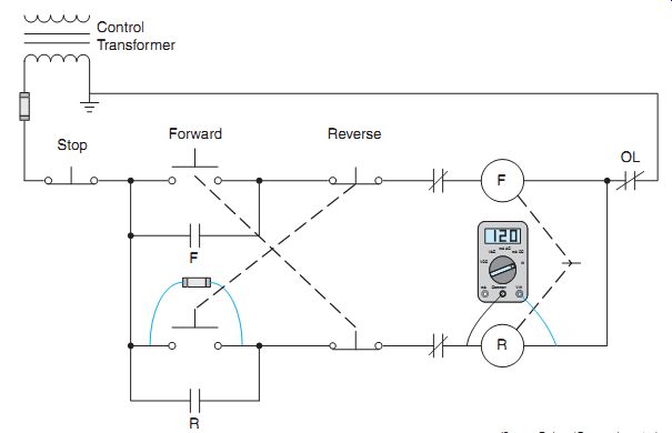
The circuit shown is a reversing starter with electrical and mechanical interlocks. Note that double-acting push buttons are used to disconnect one contactor if the start button for the other contactor is pressed. Now assume that if the motor is operating in the forward direction and the reverse push button is pressed, the forward contactor de-energizes, but the reverse contactor does not. If the forward push button is pressed, the motor will restart in the forward direction.
To begin troubleshooting this problem, make mental notes of problems that could cause this condition:
1. The reverse contactor coil is defective.
2. The normally closed F auxiliary contact is open.
3. The normally closed side of the forward push button is open.
4. The normally open side of the reverse push button does not complete a circuit when pressed.
5. The mechanical linkage between the for ward and reversing contactors is defective.
Also make mental notes of conditions that could not cause the problem:
1. The stop button is open. (If the stop button were open, the motor would not run in the forward direction.)
2. The overload contact is open. (Again, if this were true, the motor would not run in the forward direction.)
Ill. 19 A fused jumper is often used to complete a circuit when troubleshooting.
To begin checking this circuit, an ohmmeter can be used to determine if a complete circuit path exists through certain components.
When using an ohmmeter make certain that the power is disconnected from the circuit. A good way to do this in most control circuits is to remove the control transformer fuse. The ohmmeter can be used to check the continuity of the reverse contactor coil, the normally closed F contact, the normally closed section of the forward push button, and across the normally open reverse push button when it’s pressed.
The ohmmeter can be used to test the starter coil for a complete circuit to determine if the winding has been burned open, but it’s generally not possible to determine if the coil is shorted. To make a final determination, it’s generally necessary to apply power to the circuit and check for voltage across the coil. Since the reverse push button must be closed to make this measurement, it’s common practice to connect a fused jumper across the push button if there is no one to hold the button closed. A fused jumper is shown. When using a fused jumper, power should be disconnected when the jumper is connected across the component. After the jumper is in position, power can be restored to the circuit. If voltage appears across the coil, it’s an indication that the coil is defective and should be replaced or that the mechanical interlock between the forward and reverse contactors is defective.
TEST PROCEDURE EXAMPLE 3
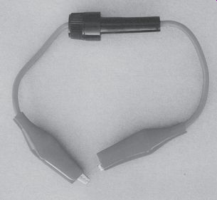
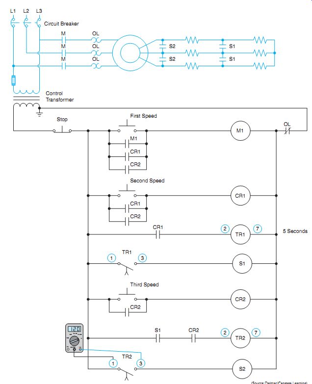
The next circuit to be discussed is shown. This circuit permits the motor to be started in any of three speeds with a 5-second time delay between accelerating from one speed to another. Regardless of which speed push button is pressed, the motor must start in its lowest speed and progress to the selected speed.
It’s assumed that eight pin on-delay timers are used to provide the time delay for acceleration to the next speed.
Assume that when the third speed push but ton is pressed, the motor starts in it lowest speed. After 5 seconds the motor accelerates to second speed but never increases to third speed.
As in the previous examples, start by making a mental list of the conditions that could cause this problem:
1. Contactor S2 is defective.
2. Timed contact TR2 did not close.
3. Timer TR2 is defective.
4. CR2 or S1 contacts connected in series with timer TR2 did not close.
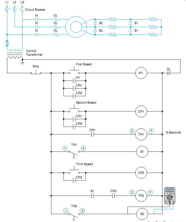
Begin troubleshooting this circuit by pressing the third speed push button and permit the motor to accelerate to second speed. Wait at least 5 seconds after the motor has reached the third speed and connect a voltmeter across the coil of S2 contactor. It will be assumed that the voltmeter indicated a reading of 0 volts. This indicates that there is no power being applied to the coil of S2 contactor. The next step is to check for voltage across pins 1 and 3 of timer TR2. If the volt meter indicates a value of 120 volts, it’s an indication that the normally open timed contact has not closed.
If timed contact TR2 has not closed, check for voltage across timer TR2. This can be done by checking for voltage across pins 2 and 7 of the timer. If a value of 120 volts is present, the timer is receiving power, but con tact TR2 did not close. This is an indication that the timer is defective and should be replaced. If the voltage across timer coil TR2 is 0, then the voltmeter should be used to determine if con tact CR2 or S1 is open.
Troubleshooting is a matter of progressing logically through a circuit. It’s virtually impossible to troubleshoot a circuit without a working knowledge of schematics. You can't determine what a circuit is or is not doing if you don't understand what it’s intended to do in normal operation. Good troubleshooting techniques take time and practice. As a generally rule, it’s easier to progress backward though the circuit until the problem is identified. For example, in this circuit, contactor S2 provided the last step of acceleration for the motor. Starting at contactor S2 and progressing backward until deter mining what component was responsible for no power being applied to the coil of S2 was much simpler and faster than starting at the beginning of the circuit and each component.
Ill. 20 Three-speed control for a wound rotor induction motor.
Ill. 21 Checking for voltage across S2 coil.
Ill. 22 Checking for voltage across pins 1 and 3 of TR2 timer.
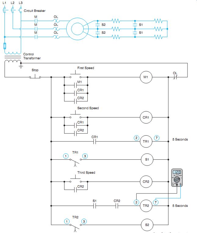
Ill. 23 Checking for voltage across TR2 coil.
QUIZ:
1. What are the three main electrical test instruments used in troubleshooting?
2. What is the advantage of a plunger-type voltage tester?
3. A motor is tripping out on overload. The motor nameplate reveals a full-load current of 68 amperes. When the motor is operating under load, an ammeter indicates the following: phase 1= 106 amperes, phase 2 = 104 amperes, and phase 3 = 105 amperes. What is the most likely problem with this motor?
4. A motor is tripping out on overload. The motor nameplate reveals a full-load current of 168 amperes. When the motor is operating under load, an ammeter indicates the following: phase 1 _ 166 amperes, phase 2 = 164 amperes, and phase 3 = 225 amperes. What is the most likely problem with this motor?
5. Refer to the circuit shown. The motor won’t start in either the forward or reverse direction when the start push buttons are pressed. Which of the following could not cause this problem?
a. F coil is open.
b. The overload contact is open.
c. The control transformer fuse is blown.
d. The stop push button is not making a complete circuit.
6. Refer to the circuit shown.Assume that the motor is running in the forward direction. When the reverse push button is pressed, the motor continues to run in the forward direction. Which of the following could cause this problem?
a. The normally open side of the reverse push button is not making a complete circuit when pressed.
b. R contactor coil is open.
c. The normally closed side of the reverse push button is not breaking the circuit when the reverse push button is pressed.
d. There is nothing wrong with the circuit. The stop push button must be pressed before the motor will stop running in the forward direction and permit the motor to be reversed.
7. Refer to the circuit shown. When the third speed push button is pressed, the motor starts in first speed but never accelerates to second or third speed. Which of the following could not cause this problem?
a. Control relay CR1 is defective.
b. Control relay CR2 is defective.
c. Timer TR1 is defective.
d. Contactor coil S1 is open.
8. Refer to the circuit shown. Assume that the third speed push button is pressed. The motor starts in second speed, skipping first speed. After 5 seconds the motor accelerates to third speed. Which of the following could cause this problem?
a. S1 contactor coil is open.
b. CR1 contactor coil is open.
c. TR1 timer coil is open.
d. S1 load contacts are shorted.
9. Refer to the circuit shown. If a voltmeter is connected across the normally open forward push button, the meter should indicate a voltage value of
a. 0 volt
b. 30 volts
c. 60 volts
d. 120 volts
10. Refer to the circuit shown. Assume that a fused jumper is connected across terminals 1 and 3 of TR2 timer. What would happen if the jumper were left in place and the first speed push button pressed?
a. The motor would start in its lowest speed and progress to second speed but never increase to third speed.
b. The motor would start operating immediately in third speed.
c. The motor would not start.
d. The motor would start in second speed and then increase to third speed.