AMAZON multi-meters discounts AMAZON oscilloscope discounts
GOALS:
• State the advantages of direct drives and pulley drives.
• Install directly coupled motor drives and pulley motor drives.
• Check the alignment of the motor and machine shafts, both visually and with a dial indicator.
• Install motors and machines in the proper positions for maximum efficiency.
• Calculate pulley sizes using the equation:
Drive revolutions per minute/Driven revolutions per minute = Driven Pulley Diameter/Drive Pulley Diameter
DIRECTLY COUPLED DRIVE INSTALLATION
The most economical speed for an electrical motor is about 1800 revolutions per minute.
Most electrically driven constant-speed machines, however, operate at speeds below 1800 rpm. These machines must be provided with either a high-speed motor and some form of mechanical speed reducer, or a low-speed, directly coupled motor. Electronic controlled drives are available, but the expense sometimes exceeds the need.
Synchronous motors can be adapted for direct coupling to machines operating at speeds from 3600 rpm to about 80 rpm with horsepower ratings ranging from 20 to 5000 and above. It has been suggested that synchronous motors are less expensive to install than squirrel cage motors if the rating exceeds 1 hp. However, this recommendation considers only the first cost. It does not take into account the higher efficiency and better power factor of the synchronous motor. When the motor speed matches the ma chine input shaft speed, a simple mechanical coupling is used, preferably a flexible coupling.
Trouble-free operation can usually be obtained by following several basic recommendations for the installation of directly coupled drives and pulley, or chain, drives. First, the motor and machine must be installed in a level position.
When connecting the motor to its load, the alignment of the devices must be checked more than once from positions at right angles to each other. For example, when viewed from the side, two shafts may appear to be in line. When the same shafts are viewed from the top, as shown in ill. 1, it is evident that the motor shaft is at an angle to the other shaft. A dial indicator should be used to check the alignment of the motor and the driven machinery, ill. 2. If a dial indicator is not available, a feeler gauge may be used.
During the installation, the shafts of the motor and the driven machine must be checked to ensure that they are not bent. Both machine and motor should be rotated together, just as they rotate when the machine is running, and then rechecked for alignment. After the angle of the shafts is aligned, the shafts may appear to share the same axis. However, as shown in ill. 3, the axes of the motor and the driven machine may really be off center. When viewed again from a position 90 degrees away from the original position, it can be seen that the shafts are not on the same axis.
To complete the alignment of the devices, the motor should be moved until rotation of both shafts shows that they share the same axis when viewed from four positions spaced 90 degrees apart around the shafts. The final test is to check the starting and running currents with the connected load to ensure that they do not exceed specifications.
There are several disadvantages to the use of low-speed, directly coupled induction motors.
They usually have a low power factor and low efficiency. Both of these characteristics increase electric power costs. Because of this, induction motors are rarely used for operation at speeds below 500 rpm.
Constant-speed motors are available with a variety of speed ratings. The highest possible speed is generally selected to reduce the size, weight, and cost of the motor. At 5 horsepower, a 1200-rpm motor is almost 50 percent larger than an 1800-rpm motor. At 600 rpm the motor is well over twice as large as the 1800-rpm motor. In the range from 1200 rpm to 900 rpm, the size and cost disadvantages may not be overwhelming factors. Where this is true, low speed, directly coupled motors can be used. For example, this type of motor is used on most fans, pumps, and compressors.
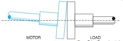
ill. 1 Every alignment check must be made from positioning 90 degrees apart,
or at right angles to each other.
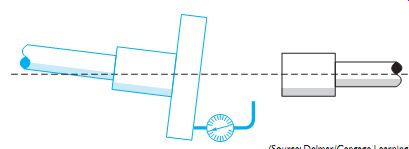
ill. 2 Angular check of direct motor couplings.
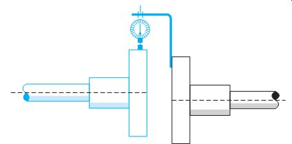
ill. 3 Axis alignment of direct motor couplings.
Laser-Computer Method of Equipment Alignment
Laser light is coherent; that is, it has a single frequency with constant amplitude and wave length, which gives it precision in many applications. Laser light is directional, traveling in a straight line, rather than radiating outward.
Construction jobs where a great deal of alignment is necessary, such as installing conveyor systems, are usually done by the conveyor manufacturer.
The laser beam method is very accurate when performed by qualified people. Once the laser beam system is targeted and set up, it re quires periodic checks to make sure it has not been bumped out of position.
Prisms can be used to bend the laser light beam at precise 90-degree angles to ease alignment of components perpendicular to the longitudinal plane. Multi-prisms can be used to "see" around obstructions. On some jobs, measurement data are entered into a computer program that models the system. The ways in which a laser can be used for aligning systems are limited only by the ingenuity of the users.
PULLEY DRIVES
Installation
Flat belts, V-belts, chains, or gears are used on motors so that smooth speed changes at a constant rpm can be achieved. For speeds below 900 rpm, it is practical to use an 1800-rpm or 1200-rpm motor connected to the driven ma chine by a V-belt or a flat belt.
Machine shafts and bearings give long ser vice when the power transmission devices are properly installed according to the manufacturer's instructions.
Offset drives, such as V-belts, gears, and chain drives, can be lined up more easily than direct drives. Both the motor and load shafts must be level. A straightedge can be used to ensure that the motor is aligned on its axis and that it is at the proper angular position so that the pulley sheaves of the motor and the load are in line, ill. 4. When belts are installed, they should be tightened just enough to ensure non slip engagement. The less cross tension there is, the less wear there will be on the bearings involved. Proper and firm positioning and alignment are necessary to control the forces that cause vibration and the forces that cause thrust.
The designer of a driven machine usually determines the motor mount and the type of drive to be used. This means the installer has little choice in the motor location. In many flat belt or V-belt applications, however, the construction or maintenance electrician may be called on to make several choices. If a choice can be made, the motor should be placed where the force of gravity helps to increase the grip of the belts. A vertical drive can cause problems because gravity tends to pull the belts away from the lower sheave, ill. 5. To counteract this action, the belts require far more tension than the bearings should have to withstand. The electrician should avoid this type of installation if possible.
There are correct and incorrect placements for horizontal drives. The location where the motor is to be installed can be determined from the direction of rotation of the motor shaft. It is recommended that the motor be placed with the direction of rotation so that the belt slack is on top. In this position, the belt tends to wrap around the sheaves. This problem is less acute with V-belts than it is with flat belts or chains.
Therefore, if rotation is to take place in both directions, V-belts should be used. In addition, the motor should be placed on the side of the most frequent direction of rotation, ill. 6.
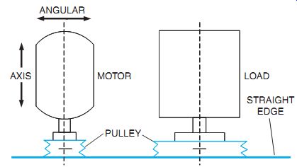
ill. 4 Using straightedge for angular and axis alignment.
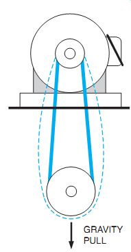
ill. 5 Greater belt tension is required in vertical drives where gravity opposes
good belt traction. This greater tension generally exceeds the tension the
bearings should withstand.
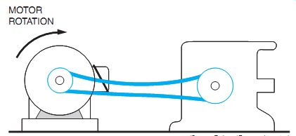
ill. 6 Direction of motor rotation can be used to advantage for good belt
traction (with slack at top) if the motor is placed in the proper position.
Pulley Speeds
Motors and machines are frequently shipped without pulleys or with pulleys of incorrect sizes.
The drive and driven speeds are given on the motor and machine nameplates or in the descriptive literature accompanying the machines.
Four quantities must be known if the machinery is to be set up with the correct pulley sizes: the drive revolutions per minute, the driven revolutions per minute, the diameter of the drive pulley, and the diameter of the driven pulley. If three of these quantities are known, the fourth quantity can be determined. For example, if a motor runs at 3600 rpm, the driven speed is 400 rpm, and there is a 4-inch pulley for the motor, the size of the pulley for the driven load can be determined from the following equation:
Drive rpm / Driven rpm = Driven Pulley Diameter/Drive Pulley Diameter
By cross multiplying and then dividing, we arrive at the pulley size required:
4X = 144 =36-inch diameter pulley
If both the drive and driven pulleys are missing, the problem can be solved by estimating a reasonable pulley diameter for either pulley and then using the equation with this value to find the fourth quantity.
QUIZ:
1. What are the disadvantages of low-speed, directly coupled induction motors?
2. What type of AC motor can be directly coupled at low rpm with larger horsepower ratings?
3. What three alignment checks should be made to ensure satisfactory and long service for directly coupled and belt-coupled power transmissions?
4. What special tools, not ordinarily carried by an electrician, are required to align a directly coupled, motor-generator set?
5. Induction motors should not be used below a certain speed rpm. What is this speed?
6. What is the primary reason for using a pulley drive?
7. How tightly should V-belts be adjusted?
8. Refer to ill. 6 and assume the motor is to rotate in the opposite direction.
How can the belt slack be maintained on top?
9. A machine delivered for installation has a 2-inch pulley on the motor and a 6-inch pulley on the load. The motor nameplate reads 180 rpm. At what speed in rpm will the driven machine rotate?