AMAZON multi-meters discounts AMAZON oscilloscope discounts
GOALS:
- Describe the method of operation of a typical electric braking controller.
- List advantages of the use of an electric brake on an AC induction motor.
- Connect electric braking controllers.
- Recommend troubleshooting solutions for electric braking problems.
APPLICATION
As a powerful production machine slowly coasts to a stop, the operator is idle. Work isn't being accomplished by either the operator or the machine.
This slow stop may be cited as a safety hazard under the occupational safety laws. There is, how ever, a simple, economical, and effective way to eliminate this type of stop to improve the safety and efficiency of the equipment. An all-electric braking controller provides an effective brake for a standard drive, AC squirrel cage motor. It will stop AC motor-driven equipment as fast as it takes to reach full speed. Operation is smooth, noise-free, and automatic. This type of controller is designed to stop motors driving high-inertia loads such as roving or spinning frames. Electric brakes can be used with conveyors, machine tools, woodworking machines, textile machinery, rubber mills, and processing machinery.
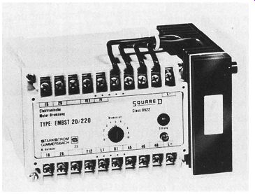
ill. 1 Solid-state braking control for starting and braking.
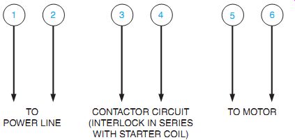
ill. 3 Typical connections for an electronic brake shown in Ill. 2.
Electric and electronic braking controllers, Ill. 1, can be installed on new or existing machines. These controllers have several advantages over conventional brakes. E.g., it's sometimes difficult to install conventional electromechanical brakes on existing equipment without extensive rebuilding. Mechanical brakes also require extensive mechanical maintenance, adjustment, and periodic replacement of worn parts.
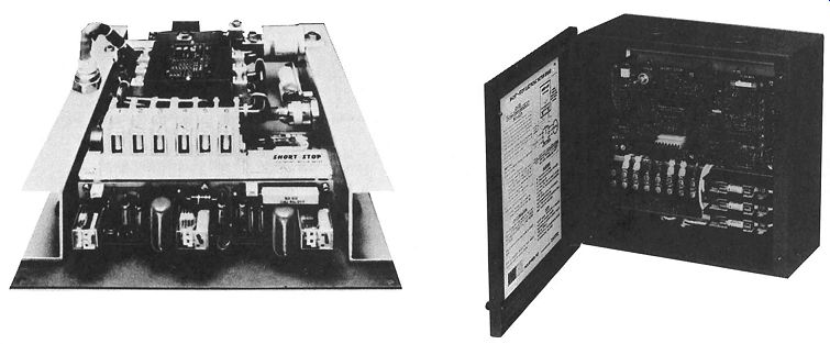
Ill. 2 shows an electronic braking control that can be added to an existing
motor starter.
Typical connections for an electronic brake are shown in Ill. 3.
OPERATION
The principle of electric braking can be applied to standard AC squirrel cage or wound rotor motors. When a motor is to be stopped, direct current is applied to one or all of the three phases of the motor after the AC voltage is removed. There is now a stationary DC field in the stator instead of an AC rotating field. As a result, the motor is braked quickly and smoothly to a standstill. An electric braking controller provides a smoother positive stop because the braking torque decreases rapidly as the speed approaches zero. Tapped resistors are sometimes used to adjust the braking torque. Controlled SCRs are also used.
Three-phase electric braking improves the efficiency of stopping and reduces the heat buildup in the motor as compared to single-phase braking.
One brake stop is equivalent to a normal start. This means that there must be a reduction in the allowable number of starts that can be made without overheating the motor.
CONSTRUCTION
A self-contained transformer and rectifier provide the direct current required for braking.
An adjustable timer is used to provide depend able timing of the braking cycle. A standard reversing starter can be used to supply power to the motor: AC during normal operation and DC during braking.
Terminal blocks are available for motor and control connections. Taps on current-limiting resistors provide a means of adjusting the braking torque over a wide range. Controllers consisting of braking units only can be obtained for use with existing motor starters.
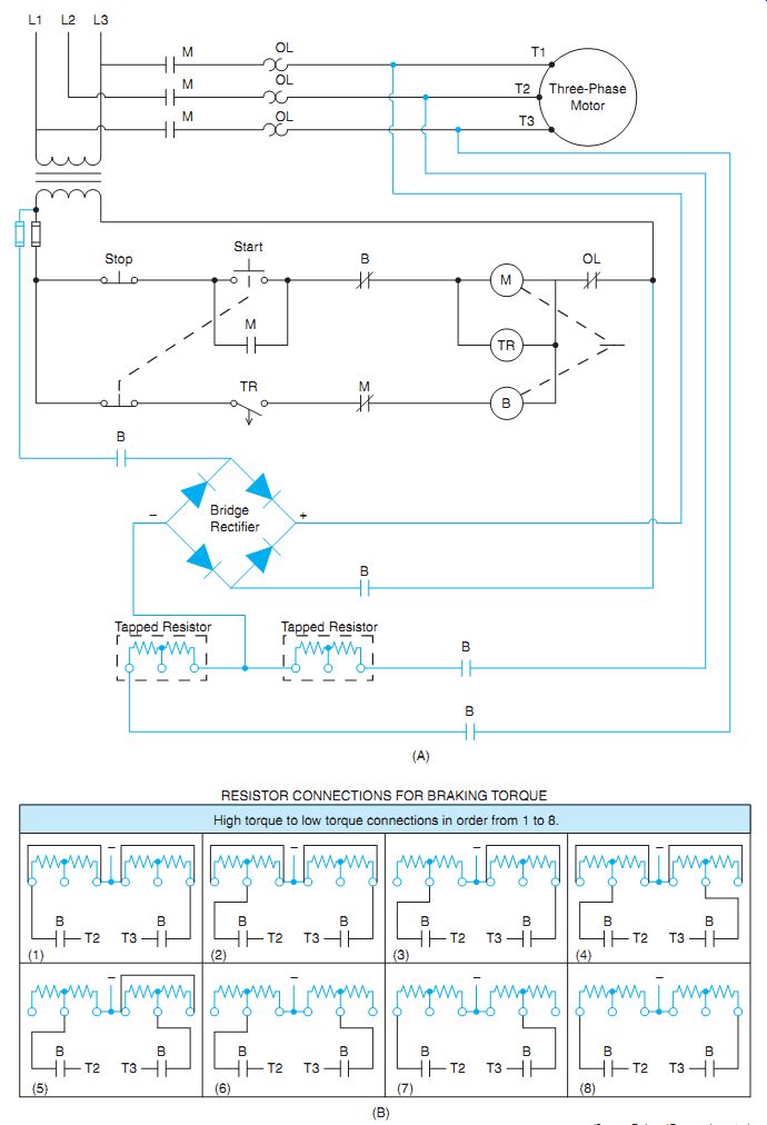
ill. 4 Typical line diagram and resistor connections for an electric braking
circuit.
SEQUENCE OF OPERATION OF AN ELECTRIC BRAKING CIRCUIT
Ill. 4(A) is the schematic diagram of a typical electric braking circuit. When motor starter M is energized, the motor operates as soon as the start button closes. The normally closed contact of the start button ensures that braking contactor B is de-energized before the motor is connected to the AC supply.
While M is energized, its normally closed interlock contact is open and its normally open time-delay contact is closed. When the stop button is pressed, M drops out. When interlock M recloses, braking contactor B is energized.
B remains energized until the time-delay contact (M) times open (time delay after de-energized). This timing contact is adjustable and should be set so that contactor B drops out as soon as the motor comes to a complete stop.
Braking contactor B connects all three motor leads to a source of direct current through the rectifier and transformer. Direct current applied to an induction motor polarizes it to a stationary magnetic field and causes it to brake to a stop. Less current is required for the same braking torque on all three phases as compared with applying direct current to one phase. More ampere turns are gained with the additional windings, conserving energy, and reducing motor heating. The braking torque and the speed of braking can be varied by reconnecting the tapped resistors as shown in Ill. 4(B).
DC and AC supplies must not be connected to a motor at the same time. The motor starter and braking contactor must have adequate interlocks. It is recommended that the motor starter always be included as an integral unit with the brake. If a braking unit only is applied to a separate motor starter, mechanical inter locking is sacrificed. In this case, the start but ton must be equipped with a normally closed contact. The motor starter must also have extra, normally closed interlock contacts.
ELECTRIC BRAKING FOR A WOUND ROTOR MOTOR
Ill. 5 illustrates a method of dynamic braking for a wound rotor induction motor developed by the author. The circuit provides three steps of automatic starting for the motor and offers three different braking methods. The three braking options are coast stop, medium stop, and rapid stop. The resistors connected to the rotor circuit used to provide the steps of acceleration for the motor when starting are used to provide the medium braking option when the motor is stopped. As a general rule, the DC voltage applied to the stator winding is kept to about 10 percent of the nameplate volt age of the motor. A current limiting resistor has been added to the DC supply to further control the DC current supplied to the stator winding during braking. Braking current shouldn't exceed the motor's starting current or overheat problems will occur.
The braking speeds for motors depend on motor ratings and the connected load. E.g., a 1-horsepower motor with a heavy inertia load such as a flywheel or conveyor can be stopped in about 1 second if necessary. A 125 horsepower, slow-speed motor can be stopped in 2 or 3 seconds if necessary. The amount of stop ping force is proportional the strength of the magnetic field developed in the stator winding by the DC supply voltage and the strength of the magnetic field developed in the rotor by the induced voltage. It is like connecting the north and south ends of two magnets together and trying to pull them apart. The force necessary to pull the magnets apart is determined by the magnetic field strength of the two magnets.
The starting sequence for the motor is as follows:
++ When the start button is pressed, a circuit's completed to M coil, causing all M contacts to close. The three load contacts close and supply power to the stator winding of the motor. One M auxiliary contact seals the circuit around the start button and the second auxiliary contact provides a current path to timer coil TR1. At this point all the resistors are connected in the rotor circuit and the motor is operating in its lowest speed.
++ At the end of TR1's time period, the normally open TR1 contact closes and provides power to the coil of S1 contactor. The two S1 load contacts close and shunt out the first set of resistors in the rotor circuit causing the motor to accelerate to second speed. The normally open S1 auxiliary contact closes and provides power to timer TR2.
++ At the end of TR2's time period, the normally open TR2 contact closes and provides power to contactor coil S2. The two S2 load contacts close and short circuit the rotor circuit causing the motor to accelerate to its highest or third speed.
If the coast stop button is pressed, M starter is de-energized and the circuit returns to it nor mal position. The motor is permitted to coast to a stop because no DC power is applied to the stator winding.
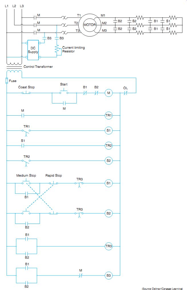
ill. 5 Dynamic braking for a wound rotor motor. The circuit provides three
braking options, coast stop, medium stop, and rapid stop.
To understand the circuit operation when the medium stop button is pressed, assume that the motor is running. The sequence is as follows:
++ When the medium stop button is pressed, a circuit's supplied to B1 contactor.
++ The two B1 load contacts close and shunt out the first set of resistors in the rotor circuit.
++ All B1 auxiliary contacts close. One auxiliary contact is connected in parallel with the medium stop button to maintain power to the circuit. A second B1 auxiliary contact provides power to timer coil TR3. TR3 limits the amount of time that DC voltage can be applied to the stator winding. The third B1 auxiliary contact closes and provides power to contactor B3.
++ Contactor B3 closes the two B3 load contacts that supply DC voltage to the stator winding.
The resistors in the rotor circuit limit the amount of induced current in the rotor circuit and therefore, limit the strength of the magnetic field developed in the rotor. It should be noted that if less braking torque is desired, the two B1 load contacts can be disconnected from the circuit. This would permit all the rotor circuit resistors to limit rotor current and further weaken the magnetic field developed in the rotor.
The rapid stop option operates in the same manner as the medium stop option except that the load contacts controlled by contactor B2 directly short the rotor circuit causing maximum rotor current and therefore, maximum magnetic field strength to be developed in the rotor.
Some other points concerning the circuit to be considered are:
++ Double acting push buttons permit the medium stop and rapid stop options to be selected after the other one has been selected.
++ Normally closed contacts controlled by contactors B1 and B2 will disconnect motor starter M from the line if either the medium stop or rapid stop option is selected.
++ A normally closed M contact connected in series with coil B3 provides interlock with the motor starter to insure that direct current and three-phase alternating current cannot be connected to the motor at the same time.
The sudden stopping of a motor by mechanical brakes can often harm the motor or load. This is especially true of gear driven loads. Dynamic braking, however, provides a very smooth braking action. Maximum braking force occurs at the beginning of the braking period because the rotor is turning at it greatest speed causing maximum induced current in the rotor. The braking torque will taper off as the motor speed decreases and becomes zero when the motor stops. Dynamic braking cannot be used to hold suspended loads such as in the case with a crane.
Dynamic braking can easily be demonstrated by applying direct current to an AC induction motor and turning the motor shaft by hand.
QUIZ:
1. Why does three-phase braking reduce motor heating as compared with single-phase braking?
2. Differentiate between the AC and DC magnetic fields applied to an induction motor stator.
3. Electric braking can be applied to what type of AC motor?
4. Why is electric braking smooth and resilient?
5. Braking current is passed through overload heaters; however, the overload control circuit contacts are in the AC starting circuit. How does this protect the motor?
6. How often can a motor be stopped using electric braking?
7. Explain why there is no danger of the motor reversing after it's braked to a stop.