AMAZON multi-meters discounts AMAZON oscilloscope discounts
In the 1970s and 1980s power supplies required higher currents and voltages than the individual diodes could provide in the basic four-diode bridge. If the amount of current or voltage the power supply requires is larger than the individual diode can provide, the diodes can be connected in parallel to provide the extra current. and they can be connected in series to meet the higher voltage specification. Two types of circuits are generally used to provide these configurations. Fig. 1a shows an example using 12 diodes that are connected in parallel as a six-phase full-wave bridge to provide extra current. Fig. 1b shows examples of 12 diodes connected in series to allow the bridge to be used in a circuit where the system voltage is higher than the specification for any of the individual diodes.
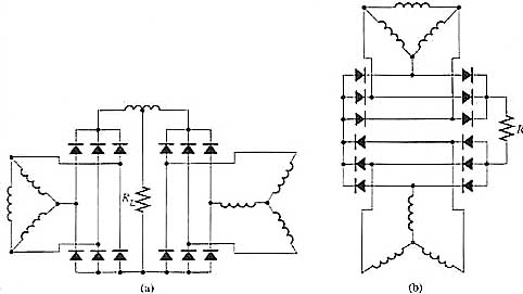
Above: Fig. 1 (a) Electronic schematic of 12 diodes connected in parallel as a six-phase full-wave bridge rectifier. This circuit can provide larger current that exceeds the specification of each individual diode. (b) Electronic schematic of 12 diodes connected in series as a six-phase full-wave bridge rectifier that provides a voltage that exceeds the specification of each individual diode.
Since both of these types of circuits use 12 diodes, the amount of ripple
in the output section is reduced to approximately 1% since the output
frequency will be 12 times the input frequency. In the circuit in Fig.
1a where the diodes are connected as two parallel power supplies that
are interconnected with equalizing reactors, each of the bridge circuits
provide half of the load. In the circuit in Fig. 1b, each phase of the
input voltage will pass through four diodes instead of two so the voltage
drop is shared four ways.

