AMAZON multi-meters discounts AMAZON oscilloscope discounts
Several other variations of the three-phase rectifier are used in some industrial power supplies because they provide an advantage of less power being converted by each individual diode, which means smaller diodes can be used to provide the same voltage and current as another rectifier circuit. Two of the more usable types of alternative rectifier circuits are shown in Figs. 1 and 2. A three-phase double-wye rectifier with an interphase transformer is shown in Fig. 1. This rectifier circuit is sometimes used instead of the normal three-phase bridge because each diode in this circuit must rectify only one-sixth of the total dc load, whereas each diode in the normal bridge circuit must contribute one-third of the dc load since it takes a pair of diodes to rectify each phase.
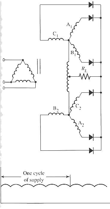
Above: Fig. 1 Electronic schematic of a three-phase
double-wye rectifier with an interphase transformer. The output waveform
for the rectifier is also shown.
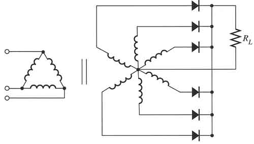
Above: Fig. 2 Electronic schematic of a six-phase
star rectifier circuit. This rectifier circuit utilizes a secondary transformer
winding that has all six windings connected at a center tap.
This circuit consists of the secondary windings of two three-phase wye-connected transformers that have their neutral points connected by an interphase transformer. The polarity of the windings of the first secondary must be reversed with respect to the polarity of the windings in the second transformer.
This means that the secondary windings of the two transformers are actually wired in inverse parallel to each other. This allows the diodes to all be connected the same wav, with their cathodes all connected together to provide the positive dc power. The interphase transformer connects the two neutral points of the wye secondary transformers and it has a center tap, which h becomes the negative terminal of the dc power supply. The output waveform for the rectifier is also shown; notice that the amount of ripple is the same as the three-phase bridge rectifier.
Keep in mind that the output waveform for the half-waves created by the three-phase sine waves will show two half-waves for the sine-wave input of each phase. This means that the output waveform will have six half-waves that will overlap because the sine waves of the three-phase input voltage overlap at 120° intervals. The overlap of the six half-waves in the output section results in a higher average dc voltage and less ripple that needs to be filtered.
Another method of connecting the secondary windings of the transformer for the three-phase rectifier is shown in Fig. 2. In this diagram notice that the secondary windings of the transformer consist of six separate windings. All six of the windings are connected at one end to form a center point for the star configuration, which is actually a type of wye-connected transformer. The cathodes of each diode in this rectifier are connected to provide the positive terminal of the dc power supply. The center point of the star is the negative terminal of the dc power supply. This circuit is used where it's important that all of the diodes in the circuit have a common connection for their cathodes.

