AMAZON multi-meters discounts AMAZON oscilloscope discounts
It's important to compare all of the different types of rectifier circuits. One will find each of these different types of circuits when one troubleshoots modern electronic controls such as ac and dc motor drives, welding power supplies, uninterruptible power supplies (UPS), and other industrial systems that require dc voltage. Fig. 1 (below) provides a table that shows all of the types of rectifier circuits that have been previously discussed and each of their characteristics are compared.
In the first line of the table notice a comparison of the average current that each diode will carry. In the four-diode bridge and in the six-phase rectifier circuit where the diodes are connected in series, each diode must carry 0.333 of IF(Av), and in all of the other circuits, each diode must carry 0.167. This means that if the current requirements for the output of the power supply are larger than the current rating of any individual diode, the circuit where the diode carries 0.167 of the full-load current should be used.
Also notice that as more diodes are used in a rectifier circuit, the ripple factor (percentage of total rms ripple) becomes better (lower). This table also shows that the conversion efficiency of each of the three-phase rectifiers is above 96%. This means that each of these types of three-phase rectifiers will produce approximately the same amount of dc voltage for a given input ac voltage.
In the examples of the single-phase power supplies the amount of dc average voltage was calculated using several equations. The equations for solving the amount of dc average voltage for three-phase rectifiers become more complex because the instantaneous values of each phase of the supply voltage must be accounted for. Thus, it's easier to use a rectification ratio for each type of three-phase power supply, which is shown in the bottom line of the table.
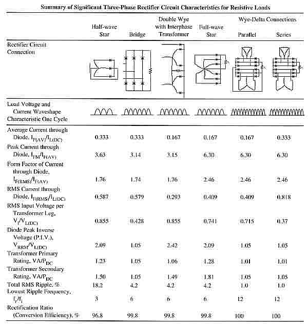
Above: Fig. 1 A table that shows the comparison of all of the features of three-phase power supplies.

